
The Anatomy of Ceiling Fan Electrical Schematics
Installing a ceiling fan is a staple DIY electrical project, but misinterpreting the manufacturer's schematic can lead to tripped breakers, damaged motors, or severe shock hazards. When reviewing wiring diagrams for ceiling fans, especially those equipped with integrated light kits, you are essentially managing two distinct loads on a single branch circuit. According to the National Electrical Code (NEC), ceiling fans are classified as appliances under Article 422, meaning they require specific support and circuit management protocols that differ from standard light fixtures.
In this 2026 appliance wiring tutorial, we will break down the exact color codes, dual-switch configurations, and hardware requirements necessary to safely wire a ceiling fan with a light kit. We will also cover the most common failure modes encountered when DIYers deviate from the schematic.
Standard Wire Color Codes and NEC Definitions
Before making any wire nut connections, you must identify the conductors in both your ceiling junction box and the fan's downrod housing. While manufacturers like Hunter, Hampton Bay, and Minka-Aire use standardized color coding, older homes may feature non-compliant legacy wiring.
- Black Wire (Ceiling & Fan): The ungrounded (hot) conductor supplying continuous power from the breaker panel. In the fan canopy, this powers the motor.
- White Wire (Ceiling & Fan): The grounded (neutral) conductor. This completes the circuit for both the motor and the light kit. NEC 200.7(C)(2) Warning: If you are working with an older switch loop, the white wire in the ceiling may actually be a hot feed. It must be re-identified with black electrical tape at both ends.
- Green or Bare Copper (Ceiling & Fan): The equipment grounding conductor. This must be bonded to the metal junction box and the fan's mounting bracket to prevent the chassis from becoming energized during a fault.
- Blue Wire (Fan Only): The dedicated hot conductor for the light kit. This is the wire that causes the most confusion in wiring diagrams for ceiling fans. It must be connected to a separate switched hot if you want independent wall control for the light.
Scenario A: Single Wall Switch (Fan and Light on One Circuit)
This is the simplest configuration, typically found in rooms where the wall switch controls power to the entire ceiling box, and the user relies on pull chains or a remote control to toggle between the fan and the light.
- Turn off power at the breaker and verify with a non-contact voltage tester.
- Connect the White (Neutral) wire from the ceiling to the White wire from the fan using a yellow wire nut (rated for 2-3 #14 or #12 AWG wires).
- Connect the Green/Bare (Ground) wires together and attach a pigtail to the green grounding screw on the fan mounting bracket.
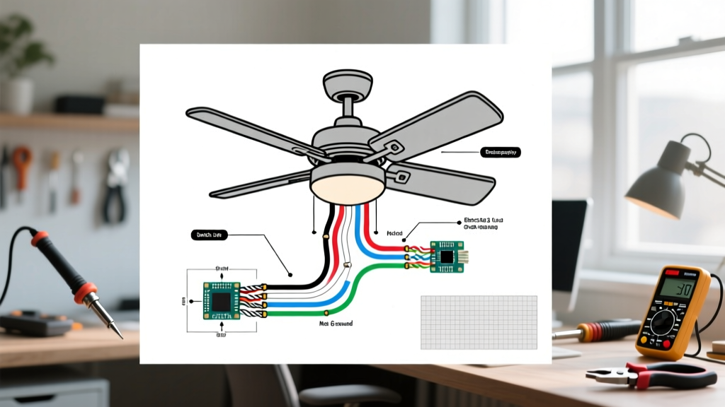
- Connect the Black (Hot) wire from the ceiling to BOTH the Black wire (fan motor) and the Blue wire (light kit) from the fan. Use a red wire nut to accommodate the three conductors securely.
- Tuck the wires into the junction box and secure the canopy.
Pro-Tip: If your single switch is a standard dimmer, you must replace it. Standard dimmers will destroy a ceiling fan motor's capacitor and cause a loud humming noise. You must use a dedicated fan speed control switch, such as the Lutron Maestro MA-FQ (retailing around $35 in 2026), which uses stepped voltage regulation rather than phase-cutting.
Scenario B: Dual Wall Switches (Independent Fan and Light Control)
This configuration allows one wall switch to control the fan motor and a second switch to control the light kit. This requires a 3-wire cable (typically 14/3 or 12/3 NM-B Romex) running from the double-gang wall switch up to the ceiling junction box.
Wiring the Dual Switch Configuration
In the ceiling box, you will have a Black (hot 1), Red (hot 2), White (neutral), and Bare (ground) wire originating from the wall switches.
- Neutral: Connect the ceiling White to the fan White.
- Ground: Connect all grounds together and to the bracket.
- Fan Motor Hot: Connect the ceiling Black wire to the fan's Black wire. This is controlled by Switch 1.
- Light Kit Hot: Connect the ceiling Red wire to the fan's Blue wire. This is controlled by Switch 2.
If your home only has a 2-wire cable (14/2 or 12/2) running to the ceiling, you cannot achieve independent wall switch control without installing a smart fan controller or a wireless relay system in the canopy, as you lack the second switched hot conductor (the red wire).
Wire Gauge and Circuit Breaker Matrix
Selecting the correct wire gauge is critical for preventing voltage drop and thermal overload. While ceiling fans draw very little amperage (typically under 1.5 amps for the motor and up to 2 amps for LED light kits), the circuit must be sized for the breaker protecting it.
| Cable Type | Wire Gauge | Max Breaker Size | Max Circuit Wattage (80% Continuous) | Typical Use Case |
|---|---|---|---|---|
| 14/2 or 14/3 NM-B | 14 AWG | 15 Amp | 1,440 Watts | Standard bedroom/living room lighting circuits |
| 12/2 or 12/3 NM-B | 12 AWG | 20 Amp | 1,920 Watts | Kitchen, bathroom, or multi-outlet shared circuits |
| 10/3 NM-B | 10 AWG | 30 Amp | 2,880 Watts | Overkill for fans; used for heavy appliances (dryers) |
Critical Hardware: Fan-Rated Junction Boxes
The most dangerous mistake DIYers make when following wiring diagrams for ceiling fans is ignoring the physical mounting hardware. Standard drywall junction boxes are only rated to hold static loads of about 10 to 15 pounds. A standard 52-inch ceiling fan weighs between 20 and 35 pounds and generates significant dynamic torque and vibration when the motor spins.
Under CPSC electrical safety guidelines and NEC 422.18, ceiling fans must be mounted to a junction box specifically listed and labeled for fan support. If you are retrofitting an older home, you must install a fan-rated brace box. The Arlington Industries FB900 or the Westinghouse Saf-T-Brace (priced between $15 and $25) feature expanding metal bars that grip the wooden joists from inside the ceiling cavity, providing a secure, code-compliant anchor that can support up to 70 pounds of dynamic weight.
Advanced Troubleshooting and Failure Modes
Even with perfect wire connections, environmental and component factors can cause operational failures. Here is how to diagnose the most common issues:
1. The Motor Hums but the Blades Won't Spin
This is rarely a wiring diagram issue and almost always a failed run capacitor. The capacitor (usually a small black or silver square block housed inside the switch cup) provides the phase shift needed to start the motor. Over time, heat degrades the dielectric fluid inside. Replacing a 5uF/250V capacitor costs less than $8 and requires simply unplugging the two-prong connector.
2. The Light Kit Flickers or Buzzes
If you wired the blue wire to a dimmer switch, ensure you are using dimmable LED bulbs. Furthermore, many modern ceiling fans feature integrated LED arrays rather than screw-in bulbs. These integrated arrays require a specific LED driver. If the driver fails, the entire light module must be replaced via the manufacturer's warranty, as they are not user-serviceable with standard 120V sockets.
3. Breaker Trips Immediately Upon Energizing
This indicates a dead short. The most common culprit in ceiling fan installations is pinched wire insulation. When pushing the wire nuts and excess slack back into the junction box, the sharp metal edges of the box can slice into the white or black wire insulation, causing the hot conductor to touch the grounded metal box. Always use a plastic junction box or ensure metal boxes are properly deburred and lined with a cable connector.
Frequently Asked Questions
Can I wire a ceiling fan to a 15-amp circuit that already powers 6 recessed lights?
Yes. A standard 52-inch fan draws roughly 0.6 to 1.2 amps, and six LED recessed lights draw about 0.5 amps combined. The total load is well under the 15-amp breaker limit. However, ensure the wiring in the ceiling box is 14 AWG or larger to match the breaker rating.
What if my ceiling only has two wires (Black and White) and no ground?
Homes built before the 1960s often lack equipment grounding conductors. According to the NEC, you can install a ceiling fan on an ungrounded circuit only if the circuit is protected by a GFCI (Ground Fault Circuit Interrupter) breaker or a GFCI receptacle upstream. You must label the fan box "No Equipment Ground." For optimal safety, consult an electrician to pull a new ground wire.
How do I integrate a smart home module into the wiring diagram?
Modern smart fans (like those from Big Ass Fans or Hunter SIMPLEconnect) have internal receivers. In these cases, the wiring diagram simplifies drastically: you connect the ceiling's Black, White, and Ground directly to the fan's corresponding inputs. The wall switch must remain in the "ON" position permanently, as the internal receiver handles all speed and light dimming via Wi-Fi or Bluetooth. For deeper insights into ceiling fan energy efficiency and smart integration, refer to the U.S. Department of Energy's ceiling fan guidelines.
Final Safety Checklist
Before securing the canopy and restoring power, verify the following:
- All wire nuts are twisted tightly; give each wire a firm tug to ensure it does not slip out.
- No exposed bare copper is visible outside the wire nuts (except for the intentional ground connections).
- The mounting bracket is fully seated and locked onto the junction box ball-socket.
- The downrod set screws are tightened securely against the motor housing yoke.
By strictly adhering to the manufacturer's wiring diagrams for ceiling fans and respecting NEC load and support requirements, you ensure a safe, quiet, and long-lasting installation.