
Decoding the Electrical Panel Wiring Diagram for Code Compliance
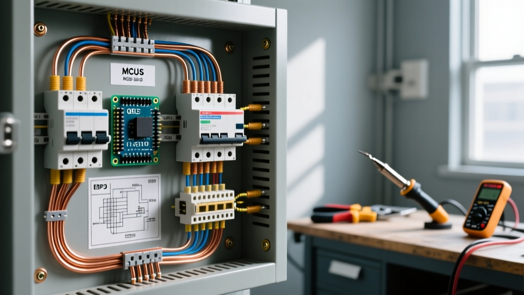
When reviewing an electrical panel wiring diagram, the primary focus for any licensed electrician or advanced DIYer must be safety and strict adherence to the National Electrical Code (NEC). A diagram is not merely a map of where wires go; it is a legal and physical blueprint that dictates fire prevention, shock mitigation, and system longevity. As we navigate the 2026 electrical landscape, understanding the intersection of schematic design and NEC mandates is non-negotiable for passing inspections and ensuring household safety.
The Anatomy of a Compliant Panel Schematic
Every standard residential or light-commercial electrical panel wiring diagram revolves around three primary bus bars: two ungrounded (hot) phase conductors, one grounded (neutral) conductor, and the equipment grounding conductor (EGC). In a standard 120/240V single-phase split system, the hot bus bars each carry 120V relative to the neutral, and 240V phase-to-phase.
Main Service Panel vs. Subpanel Diagrams
The most critical distinction in any wiring diagram is whether the panel is the main service disconnect or a downstream subpanel. According to NEC Article 250.142, the neutral and ground buses must be bonded only at the main service disconnect. In your diagram, a subpanel must show a 4-wire feed (two hots, one neutral, one ground) with the neutral bus isolated from the panel enclosure and the ground bus bonded to the enclosure. Failing to isolate the neutral in a subpanel creates a parallel neutral path, allowing return current to flow on the grounding system—a severe shock and fire hazard.
Expert Insight: Never rely on a generic diagram for a subpanel installation. Always verify the schematic explicitly shows a separate grounding bar kit (e.g., Square D PK4GTA or Eaton GBSC10) installed and bonded to the enclosure, with the factory-installed neutral bar floating via the removal of the green bonding screw or strap.
Critical NEC Mandates Reflected in Panel Diagrams
1. Working Space and Clearances (NEC 110.26)
A proper electrical layout doesn't just show internal wiring; it dictates external spatial requirements. The NEC mandates a dedicated working space around the panel. Your physical installation must maintain:
- Depth: Minimum 36 inches of clear space in front of the panel.
- Width: Minimum 30 inches, or the width of the equipment, whichever is greater.
- Height: Minimum 6.5 feet (or the height of the equipment) from the floor to the ceiling.
As noted by OSHA's electrical safety standards, these clearances must remain unobstructed at all times to ensure safe operation, maintenance, and emergency egress.
2. Torque Specifications (NEC 110.14(D))
Modern electrical panel wiring diagrams and manufacturer spec sheets now heavily emphasize termination torque. Since the 2017 NEC update and reinforced in the 2023/2026 cycles, documented torque values must be strictly followed. A loose lug causes high resistance, arcing, and ultimately a panel fire. For standard 120V plug-on or bolt-on breakers, torque specifications typically range from 20 to 25 inch-pounds. You must use a calibrated torque screwdriver (such as the Klein Tools 70550) to secure terminal screws. Hand-tightening is a direct code violation and a leading cause of thermal failures.
Wire Gauge, Breaker Sizing, and Ampacity Matrix
Matching the conductor size to the overcurrent protection device (OCPD) is the backbone of any electrical panel wiring diagram. Below is the standard compliance matrix based on copper conductors with 60°C/75°C insulation ratings (THHN/THWN-2) per NEC Table 310.16.
| Breaker Size (Amps) | Min. Copper Wire Gauge | Typical Application | NEC Reference |
|---|---|---|---|
| 15A | 14 AWG | General Lighting, Receptacles | 240.4(D) |
| 20A | 12 AWG | Kitchen/Bedroom Receptacles (AFCI) | 240.4(D) |
| 30A | 10 AWG | Water Heater, Dryer (120V feed) | 310.16 |
| 40A | 8 AWG | Electric Range, EV Charger (Level 2) | 310.16 |
| 50A | 6 AWG | Subpanel Feed, Hot Tub Spa | 310.16 |
| 100A | 3 AWG | Main Subpanel Feed | 310.16 |
Top 5 Code Violations to Avoid in Panel Wiring
When executing the physical wiring based on your diagram, inspectors frequently flag the following errors:
- Neutral and Ground on the Same Lug: NEC 408.41 strictly prohibits terminating more than one conductor on a single terminal lug unless the lug is explicitly listed and identified for multiple conductors. Neutral and ground must never share the same screw on the neutral bus bar.
- Double-Tapping on Non-Listed Breakers: Piggybacking two hot wires onto a single breaker terminal is only permitted if the breaker manufacturer explicitly designs the lug for two conductors (e.g., certain Square D QO models). Otherwise, you must use a wire nut to pigtail the conductors.
- Overcrowding and Fill Capacity: Gutters and wiring spaces inside the panel have maximum fill capacities (NEC 312.8). If wires are spilling out or preventing the dead-front cover from seating flush without pinching insulation, the installation fails.
- Missing GFCI/AFCI Protection: Modern diagrams must account for Arc Fault Circuit Interrupters (AFCI) in living spaces and Ground Fault Circuit Interrupters (GFCI) in wet locations. Using a standard breaker where an AFCI/GFCI is mandated is an immediate red tag.
- Improper Splicing in the Panel: While the panel can act as a junction box under NEC 312.8, splices must not exceed 75% of the wiring space at any cross-section. Use wire nuts and keep splices neat, accessible, and pushed to the back of the gutter.
Step-by-Step Verification Protocol Before Energizing
Before throwing the main breaker, perform this rigorous checklist to ensure your physical build matches the electrical panel wiring diagram:
- Continuity Test: With the main OFF, use a multimeter to verify there is no continuity between the neutral bus and the ground bus in a subpanel.
- Torque Audit: Double-check every lug with a calibrated torque screwdriver to the manufacturer's exact inch-pound specification.
- Dead-Front Fitment: Install the inner dead-front shield. Ensure no wire insulation is pinched and that all breaker toggles align perfectly with the cutouts.
- Voltage Verification: Energize the main. Measure phase-to-phase (should be ~240V) and phase-to-neutral (should be ~120V) at the main lugs before loading the branch circuits.
- Thermal Imaging Baseline: Once the panel is fully loaded, use a thermal camera (like the FLIR C5) to scan the bus bars and breaker terminations. Document this baseline to identify any immediate high-resistance hot spots that indicate a failed termination.
Frequently Asked Questions
Can I use an aluminum feeder wire for a 100A subpanel?
Yes. While the matrix above lists copper, NEC Table 310.16 allows 2 AWG aluminum (such as SER cable) for a 100A feeder, provided the lugs on both the main panel and subpanel are rated for 75°C aluminum conductors. Aluminum requires an anti-oxidant compound (like Noalox) applied to the stripped conductor before torquing to prevent oxidation and subsequent thermal runaway.
Does the electrical panel wiring diagram need to be posted on the door?
NEC 408.4 requires that every circuit and circuit modification be legibly identified as to its purpose on a panelboard directory. This directory must be located on the face or inside of the panel door. Generic labels like "receptacles" or "lights" are code violations; you must specify the exact area, such as "Master Bedroom AFCI Receptacles" or "Kitchen Island GFCI."
For comprehensive guidelines on residential electrical system safety and component identification, refer to the U.S. Department of Energy's electrical safety resources. Adhering strictly to your electrical panel wiring diagram and the latest NEC standards ensures a safe, reliable, and inspection-ready installation.