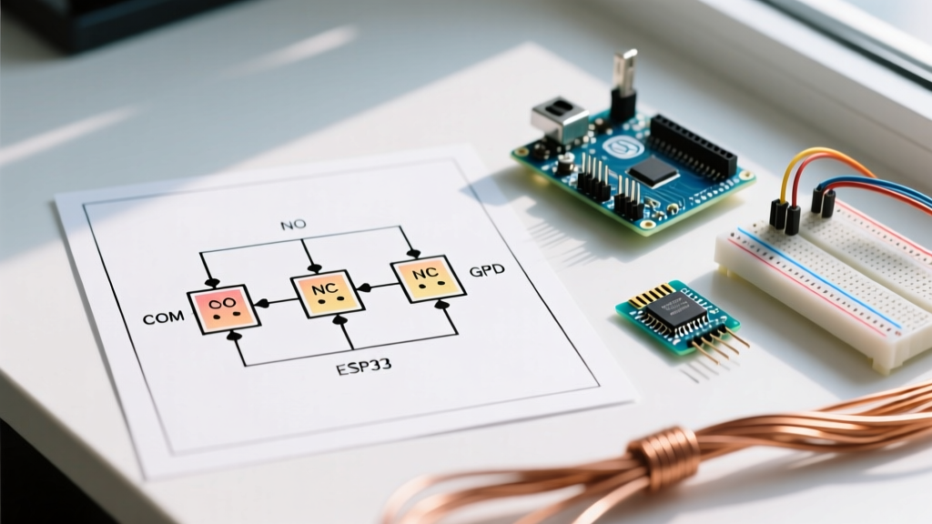

The Role of the Diagram in Relay Diagnostics
Even as solid-state relays (SSRs) gain traction in 2026 EV platforms and high-frequency industrial controllers, the standard electromechanical 4-pin and 5-pin relay remains the undisputed backbone of automotive auxiliary systems, HVAC control boards, and heavy machinery. When a high-current load fails to engage, guessing which wire is at fault leads to melted harnesses and blown fuses. Interpreting a wiring diagram for a relay transforms a chaotic bundle of wires into a logical sequence of control and load circuits, allowing you to isolate faults with surgical precision.
A relay is essentially a low-current switch operating a high-current gate. The wiring diagram splits the circuit into two distinct halves: the control circuit (the coil) and the load circuit (the contacts). Troubleshooting requires verifying both halves independently using a digital multimeter (DMM) and the schematic as your roadmap.
Decoding the DIN 72552 Standard Pinout
Before probing any terminals, you must understand the universal numbering system used on almost all ISO mini and micro relays. The DIN 72552 standard assigns specific numbers to relay pins, which are mirrored directly on your wiring diagram and the physical relay housing.
- Terminal 86: Coil Positive (+). Receives the trigger voltage (usually 12V or 24V) from a switch, ECU, or timer.
- Terminal 85: Coil Negative (-). Provides the path to ground to complete the control circuit and energize the electromagnet.
- Terminal 30: Common (COM). The main power feed from the battery or high-current bus, usually protected by a primary fuse.
- Terminal 87: Normally Open (NO). The output to the load (e.g., fuel pump, cooling fan). Connects to 30 only when the coil is energized.
- Terminal 87a: Normally Closed (NC). Connects to 30 when the relay is at rest. Disconnects when energized (found only on 5-pin relays).
4-Pin (SPST) vs. 5-Pin (SPDT) Comparison Matrix
| Feature | 4-Pin Relay (SPST - Single Pole Single Throw) | 5-Pin Relay (SPDT - Single Pole Double Throw) |
|---|---|---|
| Standard Terminals | 30, 85, 86, 87 | 30, 85, 86, 87, 87a |
| Primary Use Case | Simple ON/OFF switching (Fuel pumps, horns, lights) | Changeover circuits (Headlight high/low beam, central locking) |
| Resting State (De-energized) | Load circuit is OPEN (No continuity 30 to 87) | Power flows from 30 to 87a |
| Active State (Energized) | Power flows from 30 to 87 | Power shifts from 87a to 87 |
| Common 2026 Models | Bosch 0 332 014 150 ($4 - $7) | Hella 4RA 003 510-001 ($5 - $9) |
Step-by-Step Multimeter Troubleshooting Workflow
When utilizing a wiring diagram for a relay to diagnose a dead circuit, never remove the relay immediately. Start with in-circuit testing to verify that the harness is delivering the correct signals. According to Fluke Corporation's electrical testing guidelines, in-circuit voltage drop testing is vastly superior to simple continuity checks for identifying high-resistance faults under real-world loads.
Phase 1: Isolating the Control Circuit (Terminals 85 & 86)
- Verify Trigger Voltage: Set your DMM to DC Volts. Back-probe Terminal 86 with the red lead and a known good ground with the black lead. With the ignition or switch ON, you should read battery voltage (12.2V to 14.4V). If you read 0V, the fault lies upstream (blown control fuse, faulty switch, or broken wire).
- Verify Coil Ground: Move the red lead to Terminal 85 and the black lead to the battery positive terminal. You should again read battery voltage. If you read 0V, the ground path for the coil is broken, or the ECU driver transistor has failed.
- Measure Coil Resistance (Bench Test): Remove the relay. Set the DMM to Ohms (Ω). Probe pins 85 and 86. A healthy 12V automotive relay coil (like the Omron G8P series) will read between 65Ω and 90Ω. If you read OL (infinite), the internal coil wire is snapped. If you read below 20Ω, the coil has an internal short and will blow your control fuse.
Phase 2: Load Circuit Voltage Drop Testing (Terminals 30 & 87)
If the control circuit is flawless and you can hear the relay 'click', but the load (e.g., a 15A cooling fan) isn't running, the fault is in the high-current load circuit.
- Check Feed Voltage: Back-probe Terminal 30. You should have constant battery voltage (12.0V+). If not, check the main high-amperage fuse.
- Perform a Live Voltage Drop Test: With the relay engaged and the load attempting to draw current, place your DMM red lead on Terminal 30 and the black lead on Terminal 87.
- Analyze the Drop: A healthy relay contact will show a voltage drop of less than 0.10V (100mV). If your meter reads 0.50V or higher, the internal contacts are pitted, carbon-fouled, or micro-welded. At 15 Amps, a 0.5V drop means the relay is dissipating 7.5 Watts of heat internally (P = I × V). This localized heat will eventually melt the plastic relay socket.
Expert Insight: Never rely solely on an ohmmeter to test the load contacts (30 to 87). An ohmmeter uses less than 1mA of current to test continuity. A relay with severely burnt contacts might show 0.5Ω on an ohmmeter (which sounds like continuity), but under a real 20A load, that resistance will cause massive voltage starvation to the motor. Always test under load.
Real-World Failure Modes and Edge Cases
Even with a perfect wiring diagram for a relay, physical degradation and specific component quirks can throw off your diagnosis. Here are the edge cases that separate novices from master technicians.
The Flyback Diode Polarity Trap
Many modern 5-pin relays, particularly those used in sensitive ECU-controlled circuits (like the Hella 4RA series), contain an internal flyback suppression diode wired in parallel with the coil. This diode absorbs the inductive voltage spike when the coil is de-energized, protecting solid-state drivers.
The Trap: If you swap the 12V trigger and Ground wires on Terminals 86 and 85 on a diode-equipped relay, the diode becomes forward-biased. It will act as a dead short to ground the moment the switch is pressed, instantly blowing the control circuit fuse. If a wiring diagram indicates a diode symbol across the coil, polarity matters. Terminal 86 must be Positive, and 85 must be Negative.
Contact Micro-Welding in High-Surge Loads
When switching highly inductive loads like starter solenoids or large DC motors, the inrush current can be 5 to 10 times the running current. If a standard 30A relay is used on a circuit with a 150A inrush, the intense arcing upon closure can literally weld the copper-alloy contacts together.
Symptom: The load stays ON even when the relay is unplugged or the control circuit is turned off. The diagram will show the circuit as open, but a multimeter will show continuity across 30 and 87 with the relay completely removed from the socket, indicating the socket itself is melted and shorted, or the relay contacts are fused and stuck inside the casing.
Expert Sourcing and Replacement Specifications
When a relay fails, replacing it with an exact-match unit is critical. Substituting a 4-pin relay into a 5-pin socket without verifying the internal wiring can result in Terminal 87a feeding voltage backward into a dormant circuit. For comprehensive electromechanical relay specifications and lifecycle data, engineers frequently reference the All About Circuits technical library on relay applications, which details the differences between AC and DC coil architectures.
For industrial and PCB-mounted applications, the Omron G8P series datasheet remains the gold standard for 30A power relay specifications, detailing exact coil resistance tolerances and maximum switching capacities. In 2026, a high-quality, name-brand ISO mini relay (Bosch, Hella, Omron, or Littelfuse) will cost between $4 and $12. Avoid unbranded $1 alternatives; their internal copper windings are often undersized, leading to premature coil burnout and contact welding under standard thermal cycling.
Summary Checklist for Relay Diagnostics
- Confirm control voltage at 86 and ground at 85 (DMM DC Volts).
- Verify coil resistance is between 65Ω - 90Ω (DMM Ohms, bench test).
- Check for internal diodes before reversing 85/86 polarity.
- Measure voltage drop across 30 and 87 under load (Target: < 0.10V).
- Inspect the plastic socket for heat deformation and pin spread, which causes high-resistance connections independent of the relay itself.