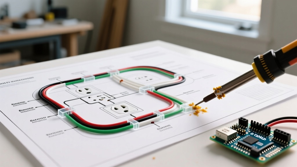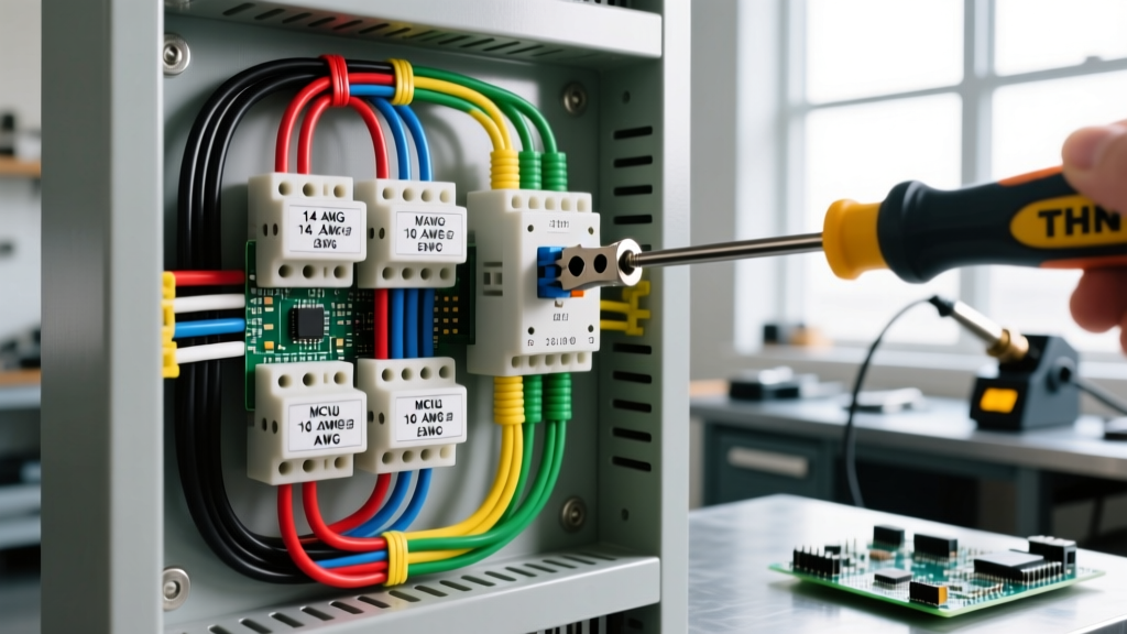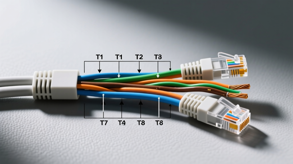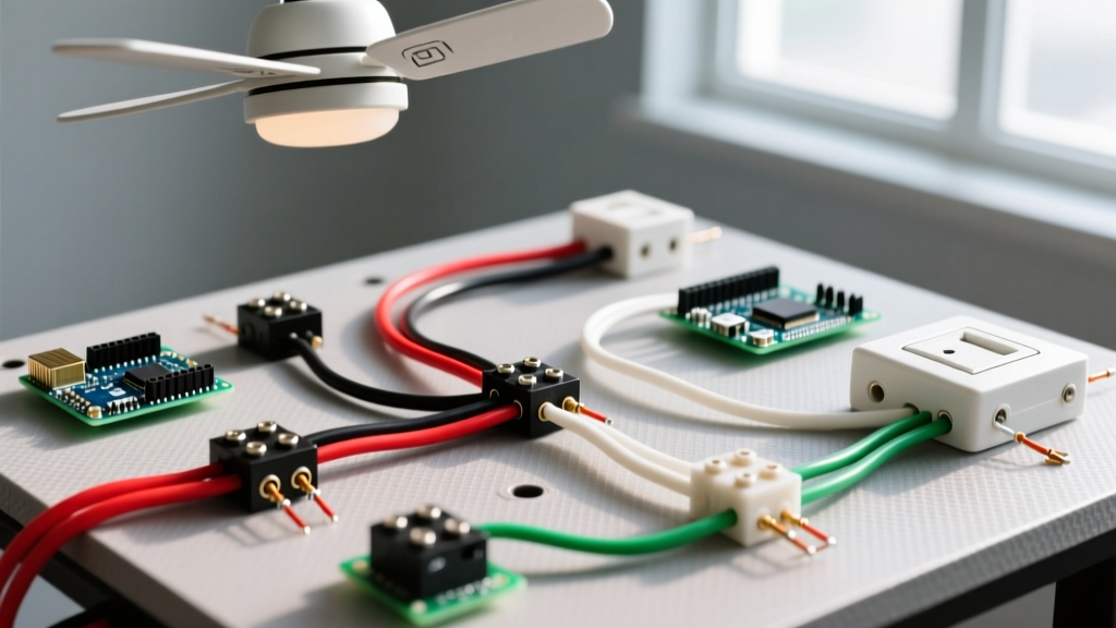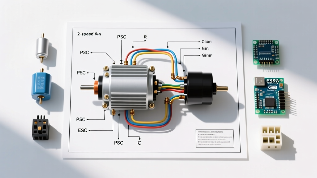

Introduction to 2-Speed Fan Motor Wiring
Whether you are retrofitting an older HVAC air handler, building a custom workshop ventilation system, or repairing a heavy-duty agricultural exhaust fan, understanding the correct wiring diagram for 2 speed fan motor configurations is essential. Most modern residential and light-commercial fan motors utilize a Permanent Split Capacitor (PSC) design. Unlike split-phase motors that require a centrifugal switch to disengage the start winding, PSC motors keep the start winding and run capacitor engaged continuously during operation. This results in smoother torque, quieter operation, and higher electrical efficiency.
In this comprehensive motor wiring tutorial, we will break down the exact terminal identification process, provide a fail-proof wiring matrix, and detail the National Electrical Code (NEC) requirements for safely integrating a 2-speed rotary switch. By the end of this guide, you will be able to confidently wire motors like the popular Dayton 1TDR7 or Fasco A067 1/2 HP blowers without relying on guesswork or faded manufacturer stickers.
Understanding the Anatomy of a 2-Speed PSC Motor
A standard 2-speed PSC fan motor typically features four primary lead wires and one ground wire. While manufacturers often use standardized color codes, never trust the wire colors blindly. Insulation dyes can vary between production runs and brands (e.g., Century vs. Fasco). The four functional terminals are:
- Common (C): The main return path for both the run and start windings. Usually connected to the Neutral line.
- Start (S): Connects exclusively to the run capacitor. This winding is physically offset to create the phase shift necessary for starting torque.
- High Speed (H): The main run winding tap with the lowest electrical resistance, allowing maximum current flow and highest RPM.
- Low Speed (L): A secondary tap on the main run winding with higher resistance, restricting current and reducing RPM.
Expert Insight: If your motor has a 3-speed or 4-speed configuration (e.g., Medium-High, Medium-Low), you can easily adapt it for a 2-speed setup. Simply cap off the unused speed taps with individual wire nuts and electrical tape to prevent accidental short circuits against the motor housing.
Essential Tools and Safety Protocols
Before touching a single terminal, you must adhere to strict safety protocols. According to OSHA's Control of Hazardous Energy (Lockout/Tagout) standards, simply flipping a wall switch is insufficient for electrical work. You must isolate the circuit at the breaker panel and apply a physical lockout device.
Required Tool List for 2026
- Multimeter: Fluke 117 True RMS (essential for accurate microfarad and low-ohm readings).
- Wire Strippers: Klein Tools 11063W (for clean stripping of 14 AWG and 12 AWG THHN).
- Run Capacitor: Genteq 97F9838 (5 MFD, 370VAC) — typically priced between $14 and $22 in 2026.
- Speed Switch: 2-position rotary fan speed switch (rated for minimum 5A at 120V/240V).
- Wire Nuts: Ideal 341 In-Sure push-in connectors (preferred over twisted wire nuts for solid-strand THHN).
Step 1: Identify Terminals via Ohm Testing
The most critical step in executing any wiring diagram for 2 speed fan motor setups is verifying the windings. Set your Fluke 117 to the Ohms (Ω) setting. You will measure the resistance between the Common wire and every other wire. Record your findings.
- Common to High (C-H): Should show the lowest resistance (typically 2.0Ω to 4.5Ω).
- Common to Low (C-L): Should show slightly higher resistance (typically 5.0Ω to 9.0Ω).
- Common to Start (C-S): Should show the highest resistance (typically 10.0Ω to 18.0Ω).
- High to Low (H-L): Should equal the sum of C-H and C-L minus the common junction overlap.
If any reading shows 'OL' (Open Loop) or infinite resistance, the internal thermal overload has tripped, or the winding is burnt out. Allow the motor to cool for 45 minutes and retest before condemning it.
Step 2: Wiring the Capacitor and Speed Switch
Once terminals are verified, proceed with the physical connections. Ensure your circuit is locked out. For a standard 120V AC single-phase system using 14 AWG THHN copper wire (compliant with NEC Article 240.4(D) for overcurrent protection), follow this sequence:
The Capacitor Connection
The run capacitor requires two connections. It is non-polarized, meaning either terminal can be used for either wire.
- Connect the motor's Start (S) wire to Terminal 1 on the run capacitor.
- Connect the motor's Common (C) wire to Terminal 2 on the run capacitor.
The Speed Switch and Line Connections
The speed switch acts as a router for the Hot (Line) voltage, directing it to the appropriate winding tap based on the desired airflow.
- Connect the incoming Hot (Black) wire from the breaker panel to the Common (Line) terminal on the 2-speed rotary switch.
- Connect a jumper wire from the switch's High Output terminal to the motor's High (H) wire.
- Connect a jumper wire from the switch's Low Output terminal to the motor's Low (L) wire.
- Connect the incoming Neutral (White) wire directly to the motor's Common (C) wire (this shares the connection point with the capacitor).
- Connect the bare copper or green Ground wire to the motor's metal chassis grounding screw.
Wiring Matrix: Terminal to Component Mapping
Use this quick-reference table on the job site to verify your connections before energizing the circuit.
| Motor Terminal | Typical Wire Color | Destination Component | Function / Notes |
|---|---|---|---|
| Common (C) | White | Neutral Line & Capacitor | Main current return path. Must be securely torqued. |
| Start (S) | Yellow or Brown | Run Capacitor Only | Creates phase shift. Never connect directly to Line voltage. |
| High (H) | Black | Speed Switch (High Tap) | Lowest winding resistance; maximum RPM and CFM. |
| Low (L) | Red or Blue | Speed Switch (Low Tap) | Higher winding resistance; reduced RPM and static pressure. |
| Ground (G) | Green / Bare | Chassis / Ground Bus | Required by NEC 250.110 for fault current clearing. |
Troubleshooting Common Failure Modes
Even with a perfect wiring diagram for 2 speed fan motor applications, components degrade. Here is how to diagnose the three most common field failures:
1. Motor Hums but Will Not Spin
This is almost always a capacitor failure or seized bearings. Disconnect power, safely discharge the capacitor using a 20k-ohm 5-watt resistor, and test it with your multimeter's capacitance setting (MFD/µF). A 5 MFD capacitor should read between 4.5 and 5.5 µF. If it reads below 4.0 µF or shows a short, replace it immediately. If the capacitor tests fine, manually spin the shaft; if it feels gritty, the sealed bearings have failed and the motor must be replaced.
2. Motor Runs on High, but Stalls on Low
This indicates an open circuit in the low-speed tap winding. Measure the resistance between Common and Low. If your meter reads 'OL', the internal copper wire has snapped, usually right at the stator connection point. The motor is non-repairable and requires replacement.
3. Motor Overheats and Trips Internal Thermal Overload
Overheating on a PSC motor is frequently caused by installing the wrong capacitor size. If a technician mistakenly installs a 10 MFD hard-start capacitor instead of a 5 MFD run capacitor, the start winding will draw excessive current and overheat within 15 minutes. Always verify the MFD and VAC ratings printed on the motor's data plate. Furthermore, ensure the blower wheel is clean; excessive dust buildup increases aerodynamic drag, forcing the motor to draw higher amperage.
Code Compliance and Best Practices
When installing or modifying motor circuits, adherence to the National Electrical Code is non-negotiable. Per NEMA MG 1 standards and NEC Article 430, motor circuits must be protected by appropriately sized overcurrent devices. For a 1/2 HP, 120V motor drawing approximately 9.8 amps at full load, a 15-amp breaker with 14 AWG wire is standard. However, if the motor is located more than 50 feet from the panel, you must upsize to 12 AWG wire to mitigate voltage drop, which can severely reduce the starting torque of a PSC motor.
Additionally, all unused speed taps must be individually insulated. Tying unused taps together and capping them as a single bundle can create a shorted transformer effect within the stator, leading to catastrophic winding failure and a potential fire hazard.
Frequently Asked Questions
Can I use a dimmer switch to control a 2-speed fan motor?
No. Standard TRIAC-based light dimmers chop the AC sine wave, which causes PSC motors to overheat, hum violently, and eventually fail. You must use a dedicated fan speed control switch designed for inductive motor loads, or rely on the physical winding taps as outlined in this tutorial.
Does the run capacitor polarity matter?
Standard AC run capacitors (the oval or round metal cylinders) are non-polarized. You can connect the Start and Common wires to either terminal. However, if you are using a dual run capacitor (which has three terminals: C, HERM, and FAN), you must connect the Common wire to 'C' and the Start wire to 'FAN'.
What happens if I wire High and Low together?
Connecting both the High and Low taps to the Line voltage simultaneously will create a short circuit across a portion of the main winding. This will instantly trip your breaker and likely burn out the winding, destroying the motor.