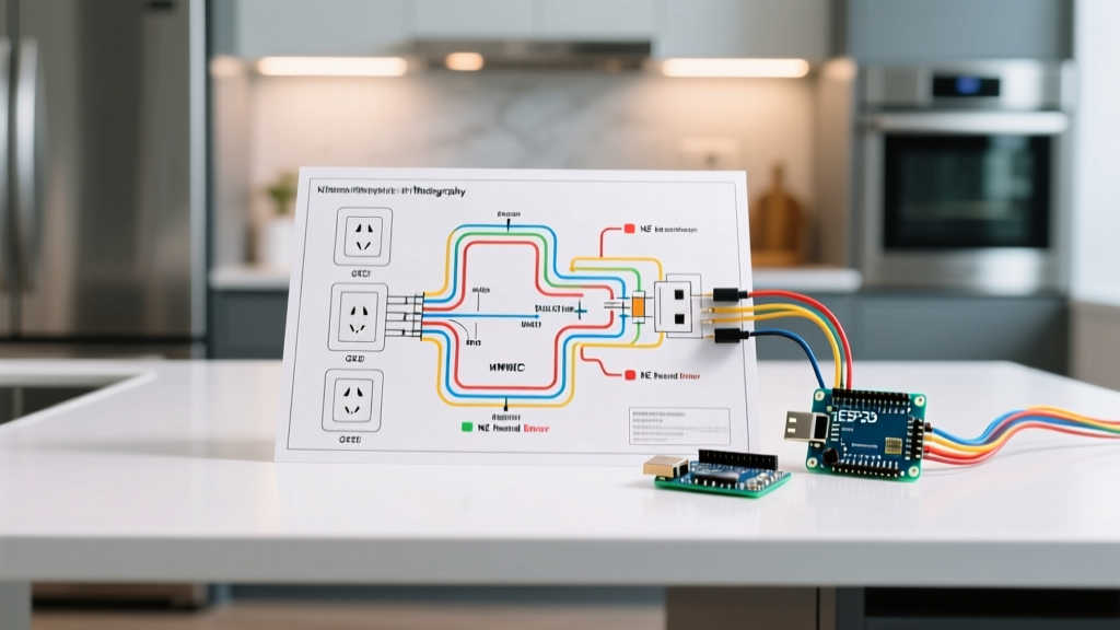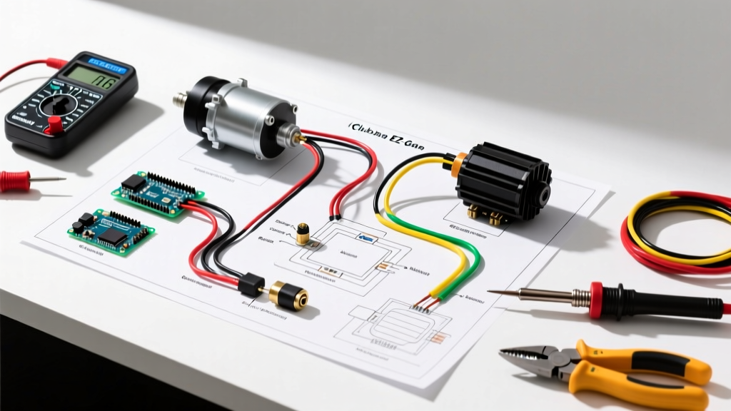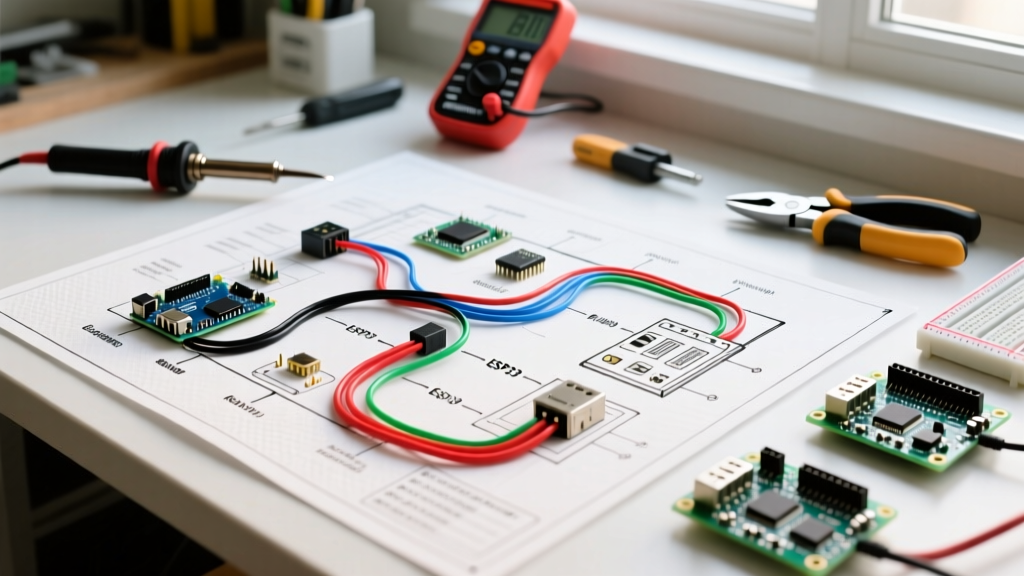

Introduction to LEV Acceleration Control
When repairing, upgrading, or building a custom light electric vehicle (LEV), referencing an accurate thumb throttle electric scooter throttle wiring diagram is the critical first step to ensure both performance and rider safety. Unlike older potentiometer-based systems that suffered from mechanical wear and contact noise, modern electric scooters rely on solid-state magnetic sensing. A misunderstood pinout or an incorrectly spliced wire can result in a 'runaway' motor, immediate controller failure, or a stranded vehicle.
This comprehensive diagram reference breaks down the internal architecture of thumb throttles, standardizes the notoriously inconsistent wire color codes, and provides actionable multimeter testing protocols for DIYers and professional repair technicians in 2026.
The Core Mechanism: Linear Hall Effect Sensors
To understand the wiring diagram, you must first understand the component generating the signal. Inside the plastic housing of a thumb throttle sits a small neodymium magnet attached to the lever arm, positioned over a linear Hall effect integrated circuit (IC). Common ICs include the Honeywell SS49E or the Diodes Incorporated AH3503.
As the rider pushes the thumb lever, the magnet rotates, altering the magnetic flux density passing through the silicon die. The Hall IC translates this magnetic field into a ratiometric analog voltage signal. According to All About Circuits, ratiometric sensors scale their output voltage proportionally to the supply voltage, making them highly stable for battery-powered applications where the 5V reference rail might experience minor sags under heavy load.
Decoding the Wiring Configurations
While the physical shape of thumb throttles varies between brands like Bafang, VESC-compatible setups, and generic Chinese square-wave controllers, the electrical topologies generally fall into two categories: 3-wire and 5-wire systems.
The Standard 3-Wire Configuration
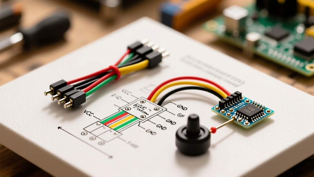
The 3-wire setup is the industry standard for pure acceleration control. It requires only a power supply, a ground reference, and the signal return.
- Wire 1 (VCC): +5V Reference voltage from the controller's internal voltage regulator.
- Wire 2 (GND): Signal ground (must be tied to the controller's logic ground, not the high-current battery ground).
- Wire 3 (Signal): The analog output wire carrying the variable voltage back to the controller's MCU ADC pin.
The 5-Wire Configuration (Cruise & Battery Indicator)
Many premium or feature-rich scooters utilize a 5-wire harness. This diagram includes the standard 3-wire throttle circuit but adds two auxiliary pins:
- Wire 4 (Cruise Control): Often a digital trigger or a secondary voltage divider that tells the controller to maintain the current speed.
- Wire 5 (Battery Level/Cruise LED): Provides a raw battery voltage feed or a switched ground to illuminate the thumb throttle's built-in LED battery gauge.
Master Pinout & Voltage Reference Table
The most common point of failure in DIY scooter builds is assuming wire colors are universal. They are not. A red wire on a generic AliExpress throttle might be +5V, while on a specific Bafang harness, it might be the signal return. Always verify with a multimeter. Below is the standard voltage expectation matrix for a properly functioning 3-wire thumb throttle.
| Pin Function | Common Wire Colors | Voltage at Idle (Released) | Voltage at Full Throttle | Tolerance / Controller Threshold |
|---|---|---|---|---|
| VCC (+5V) | Red, Yellow | 4.9V - 5.1V | 4.9V - 5.1V | Must not drop below 4.7V under load |
| GND (Logic) | Black, Blue | 0.0V | 0.0V | Max 0.05V variance from controller ground |
| Signal Out | Green, White, Orange | 0.8V - 1.1V | 3.6V - 4.2V | Idle >1.2V triggers 'Error 02' on most MCUs |
Expert Warning: Never connect the 5V VCC wire to the main battery pack voltage (e.g., 36V, 48V, or 52V). Doing so will instantly destroy the internal Hall IC and may send high voltage back into your motor controller's low-voltage logic board, frying the microprocessor.
Step-by-Step Controller Integration & Connectors
In 2026, the industry has largely standardized around two types of connectors for throttle integration. Understanding these is vital when adapting a wiring diagram to your specific hardware.
- JST-SM Connectors (2.54mm Pitch): Common on aftermarket kits, VESC enclosures, and DIY builds. They are easy to crimp but lack weatherproofing. Use 18AWG silicone wire for the pigtails to prevent voltage drop over long runs.
- Higo / Z810 Waterproof Connectors: The standard for OEM commercial scooters (e.g., Segway Ninebot, Apollo, NAMI). These feature IP67-rated O-ring seals and gold-plated pins. When splicing a Higo connector, use a specialized Higo crimping tool; standard needle-nose pliers will deform the terminal and compromise the waterproof seal.
Integration Steps:
- Power on the motor controller without the throttle connected.
- Set your multimeter to DC Voltage. Probe the controller's throttle harness to identify the +5V and GND pins. (The pin showing +5V relative to another pin is VCC; the one showing 0V is GND).
- Identify the Signal pin (it will typically read 0V or float erratically when unconnected).
- Match the controller pins to your thumb throttle pins based on your multimeter readings, ignoring the wire colors if they conflict.
- Solder and seal with adhesive-lined marine heat shrink.
Advanced Multimeter Diagnostics & Failure Modes
When a scooter exhibits erratic behavior, the thumb throttle is often blamed, but the root cause may lie in the wiring harness or the controller's 5V rail. Here is how to diagnose specific failure modes using a standard digital multimeter (DMM).
Failure Mode 1: 'Ghost' Acceleration or Error 02 at Startup
Symptom: The scooter display turns on, immediately throws an Error 02 (Throttle Fault), and refuses to arm the motor. Alternatively, the motor engages slightly without touching the lever.
Diagnosis: Most modern controllers require the throttle signal to be below 1.2V at startup to arm safely. If your idle voltage reads 1.4V or higher, the controller rejects it. This is usually caused by a ground loop or a poor ground connection. Measure the voltage between the throttle GND pin and the battery's negative terminal. If you read more than 0.1V, your logic ground is compromised. Re-crimp the ground terminal at the controller side.
Failure Mode 2: Dead Zones and Stuttering
Symptom: The scooter accelerates smoothly from 0-20%, then stutters, cuts out, and resumes at 80%.
Diagnosis: This indicates physical damage to the internal Hall IC or a failing neodymium magnet that has cracked or shifted on the lever pivot. As noted by Ebikeschool.com, physical shock from drops or crashes can misalign the magnet. The only reliable fix is replacing the throttle unit, as recalibrating the magnetic gap is nearly impossible without an oscilloscope and custom 3D-printed jigs.
Failure Mode 3: 5V Rail Sag Under Load
Symptom: Throttle response is sluggish, and the top speed is noticeably reduced when climbing hills.
Diagnosis: The controller's internal 5V linear voltage regulator (LDO) is overheating or failing, causing the reference voltage to drop from 5.0V down to 4.2V. Because the Hall sensor is ratiometric, its maximum output drops proportionally. The controller interprets this lower maximum voltage as 'partial throttle.' Check the 5V pin while the motor is under heavy load. If it drops below 4.7V, the controller's LDO requires repair or replacement.
Safety Protocols: Braking Overrides and Failsafes
A properly wired thumb throttle must always be subordinate to the vehicle's braking system. In any robust wiring diagram, the electronic brake levers (e-brakes) feature a dedicated 2-wire or 3-wire harness that connects to the controller's 'Brake Cut-Off' pins.
When an e-brake is pulled, it physically pulls the controller's brake logic pin to ground (or high, depending on active-low/active-high configuration). This hardware interrupt immediately overrides the throttle signal, disabling the MOSFET gate drivers regardless of the voltage present on the throttle signal wire. Never bypass or zip-tie your brake cut-off switches to bypass an error code; doing so removes this critical hardware failsafe and relies entirely on software latency to stop the vehicle, which is unacceptable for rider safety.
Summary and Component Sourcing
Understanding the nuances of the thumb throttle electric scooter throttle wiring diagram elevates your troubleshooting from simple parts-swapping to precise electrical diagnostics. Always verify pinouts with a multimeter, respect the 0.8V-4.2V signal envelope, and ensure your logic grounds are pristine. For replacement components, expect to pay between $14 and $28 for high-quality IP67-rated Higo throttles, while basic JST-SM models range from $8 to $15. For deeper component-level datasheets and circuit theory, refer to resources like Components101 to understand the exact silicon driving your ride.