
The Shift to 240V Water Heating in Modern Motorhomes
As the RV industry moves toward all-electric luxury motorhomes and high-end fifth wheels in 2026, the reliance on propane is rapidly diminishing. Class A diesel pushers and large toy haulers equipped with 50-amp shore power capabilities are increasingly adopting residential-style 240V electric water heaters. These units offer superior recovery rates compared to standard 120V RV elements, providing endless hot showers for full-time travelers. However, wiring a 240V system inside a high-vibration, mobile environment requires strict adherence to both the NFPA 1192 Standard for Recreational Vehicles and NEC Article 551. This guide provides a comprehensive motorhome 240v electric water heater thermostat wiring diagram, tailored specifically for the unique electrical architecture of recreational vehicles.
Understanding the 50-Amp RV Split-Phase Power Paradigm
Unlike a standard residential home where 240V is derived from a center-tapped transformer, a motorhome receives its 240V via a 50-amp NEMA 14-50 shore power cord. This cord carries two 120V hot legs (L1 and L2) that are 180 degrees out of phase, a neutral, and a ground. When measured across L1 and L2, you get 240V. The water heater thermostat must be wired across these two hot legs, bypassing the neutral entirely for a purely resistive 240V load.
CRITICAL SAFETY WARNING: Never attempt to wire a 240V water heater in an RV equipped with only a 30-amp (120V single-phase) shore power cord. Attempting to step up 120V to 240V using standard autotransformers for high-wattage resistive heating loads violates RV Industry Association (RVIA) Standards and poses a severe fire hazard.
Component Breakdown & 2026 RV Pricing Matrix
Upgrading or replacing the thermostat and associated wiring in a motorhome requires marine-grade or RV-specific components to withstand vibration and temperature fluctuations. Below is the current pricing and specification matrix for a standard 4500W 240V RV water heater setup.
| Component | Recommended Model / Spec | Estimated Cost (2026) | RV-Specific Notes |
|---|---|---|---|
| Double-Pole Thermostat | Camco 40601 Dual Element / Honeywell TH106 | $55.00 - $72.00 | Must include manual reset High-Limit (ECO) switch. |
| Circuit Breaker | Square D Homeline 30A 2-Pole (HOM230) | $32.00 | Requires 2 full slots in the RV main distribution panel. |
| Wire (10 AWG) | Marine-Grade Tinned Copper THHN (Stranded) | $2.10 / ft | Tinned copper prevents black-wire corrosion in humid RV bays. |
| Heating Element | Camco 02143 4500W 240V (Incoloy) | $48.00 | Incoloy resists dry-firing burnout better than standard copper. |
| Terminal Lugs | #10 Ring Terminals (Heat Shrink) | $12.00 / pack | Vibration-resistant heat shrink prevents short circuits. |
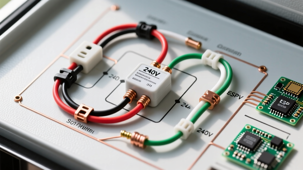
Step-by-Step: Motorhome 240v Electric Water Heater Thermostat Wiring Diagram
Follow this precise routing sequence to ensure your thermostat correctly modulates power to the heating element while maintaining critical over-temperature protection.
Phase 1: Main Panel to Thermostat Line Terminals
- Shut Off Shore Power & Inverter: Disconnect the 50-amp shore cord and turn off the main battery disconnect to prevent inverter backfeed.
- Route the 10 AWG Cable: Run two 10 AWG hot wires (typically Black and Red) from the 30A double-pole breaker in your RV sub-panel to the water heater access bay. Secure the wire every 18 inches using cushion-clamp wire ties to prevent chafing against the steel chassis.
- Connect to Thermostat Line Terminals: Attach the Black wire (L1) to the L1 terminal on the thermostat. Attach the Red wire (L2) to the L2 terminal. Torque terminal screws to 12 in-lbs to prevent vibration loosening.
Phase 2: Thermostat Load Terminals to Heating Element
- Wire the Upper Element (if applicable): For dual-element setups, route wires from Load 1 and Load 2 on the thermostat to the upper element terminals.
- Single Element Routing: If using a single 4500W element, connect the wire from Load 1 to one terminal of the heating element, and the wire from Load 2 to the other terminal.
- Integrate the High-Limit (ECO): Most RV thermostats feature a secondary High-Limit switch in series with L1. Ensure the jumper wire between the thermostat and the ECO reset button is secured with a star washer to maintain continuity over rough roads.
Phase 3: Grounding & Bonding
- Run a bare 10 AWG copper ground wire from the RV chassis grounding bus bar directly to the water heater tank grounding lug.
- Do not rely on the mounting bolts for a ground path; RV water heater bays often accumulate road grime and rust, creating high-resistance ground faults.
RV-Specific Edge Cases & Vibration Failure Modes
Wiring a 240v electric water heater in a stationary home is forgiving. In a 40-foot motorhome cruising at 70 MPH, the electrical system is subjected to constant harmonic vibration. Here are the most common failure modes we see in the field and how to prevent them:
1. Terminal Back-Out and Arcing
Vibration causes standard screw terminals to loosen, leading to micro-arcing, melted thermostat housings, and eventual fires. Solution: Always use crimped, heat-shrink insulated fork or ring terminals on your stranded wire ends. Apply a drop of medium-strength threadlocker (Loctite 243) to the thermostat terminal screws before tightening.
2. Voltage Drop Over Long Wire Runs
In large Class A motorhomes, the distance from the main breaker panel to the rear-mounted water heater bay can exceed 45 feet. A standard 10 AWG wire will experience a voltage drop of nearly 4% over a 90-foot round trip at 18.75 Amps (4500W / 240V). Solution: Upsize your wire to 8 AWG marine-grade tinned copper for any run exceeding 35 feet to maintain optimal voltage at the element.
3. The 'Dry Fire' Element Burnout
When winterizing or draining the RV water system, travelers often forget to flip the 240V water heater breaker off. If the thermostat calls for heat while the tank is empty, the element will burn out in seconds. Solution: Install a 240V flow-switch interlock or a smart relay (like the Victron Digital Multi Control) that physically prevents the thermostat from receiving L1/L2 power unless the 12V water pump is actively pressurized.
Inverter Bypass & Solar Integration Considerations
A common question among off-grid RVers is whether a 240V water heater can be powered by solar and lithium battery banks. Standard 12V or 24V DC-to-AC inverters cannot natively produce 240V split-phase power. To run this setup off-grid, your motorhome must be equipped with a specialized 240V split-phase inverter system, such as dual synchronized Victron Quattro 48/10000 units configured in split-phase mode.
Even with a 240V inverter setup, a 4500W water heater will pull nearly 190 Amps from a 24V battery bank or 95 Amps from a 48V bank. Most RV transfer switches are programmed to bypass the inverter entirely for 240V loads, routing shore power or generator power directly to the water heater thermostat to prevent catastrophic battery depletion. Always verify your automatic transfer switch (ATS) wiring diagram to ensure the 240V leg is not being routed through a 120V-only inverter relay.
Frequently Asked Questions (FAQ)
Can I use a standard residential 240V thermostat in my motorhome?
Yes, but with caveats. Residential thermostats (like those for Rheem or AO Smith tanks) lack the vibration-dampening terminal blocks found in RV-specific models like the Camco 40601. If you use a residential unit, you must apply threadlocker to the screws and use ring terminals rather than wrapping bare wire around the screws.
Why is my 240V water heater only getting 120V at the element?
This indicates a loss of one of the hot legs (L1 or L2). Check the 30A double-pole breaker in your RV sub-panel; it is common for one pole to trip while the other remains closed due to a weak internal handle-tie mechanism. Additionally, inspect the shore power pedestal and your 50-amp power cord for burned or pushed-back pins on the L1 or L2 prongs.
What is the correct multimeter resistance reading for a healthy 240V element?
Set your multimeter to Ohms (Ω). A healthy 4500W 240V heating element should read between 12.5 and 13.5 Ohms. A reading of 'OL' (Open Loop) indicates a broken internal wire, while a reading near 0.0 indicates a dead short requiring immediate replacement.