
Decoding the Schematic: GE Air Conditioner Wiring Fundamentals
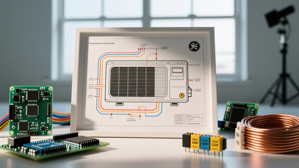
When a GE cooling system fails, guessing which component is at fault leads to wasted time and unnecessary parts swapping. Whether you are servicing a legacy GE AEQ series window unit, a GE Profile central split system, or a 2026-compliant GE ductless inverter mini-split, the factory schematic is your primary diagnostic tool. A wiring diagram for GE air conditioner systems is not merely a routing map; it is a logical flowchart detailing voltage paths, safety interlocks, and control logic. In modern HVAC repair, understanding how to trace these circuits with a digital multimeter (DMM) is mandatory for accurate, cost-effective troubleshooting.
Before opening any electrical panel, verify the unit's specific model number (e.g., AE18DQ150, ASV18DQ) and download the exact revision of the schematic. GE frequently updates control board revisions mid-production run, meaning a 2024 board may have different terminal designations than a 2026 board for the exact same chassis. Always cross-reference the physical wiring labels with the official GE Appliances support documentation before applying power.
GE Wire Color Code & Terminal Matrix
While the National Electrical Code (NEC) dictates standard colors for line and neutral voltages, GE utilizes specific color conventions for low-voltage control circuits and internal component routing. Misinterpreting these can result in immediate control board failure upon startup.
| Wire Color | Terminal Label | Function / Circuit Path | Typical Voltage |
|---|---|---|---|
| Black | L1 / COMP | Main Line Voltage to Contactor / Compressor Run | 120V / 240V AC |
| White | N / C | Neutral (Window/PTAC) or Compressor Common (Split) | 120V / 240V AC |
| Red | R / Y1 | 24V Hot from Transformer / Compressor Contactor Coil | 24V AC |
| Yellow | Y / Y2 | Cooling Call Signal from Thermostat to Control Board | 24V AC |
| Blue | C / O | 24V Common / Reversing Valve (Heat Pump Models) | 24V AC |
| Orange | DFM / ECM | DC Feedback Signal from ECM Blower Motor | 0-5V DC |
Diagnostic Workflows: Tracing the Diagram
Use the following step-by-step workflows to isolate failures using the schematic as your guide. These procedures assume you have already verified that the primary disconnect is closed and the unit is receiving correct line voltage.
1. Tracing the Compressor Circuit (Single & Dual Run)
The most common failure in standard GE split systems and large window units is the compressor hard-start or capacitor degradation. Locate the COMP, HERM, and FAN terminals on the schematic, which correspond to the dual run capacitor (commonly GE part number WR87X29155, rated at 45+5 MFD).
- Capacitor Testing: Disconnect power and safely discharge the capacitor using a 20k-ohm 5-watt resistor. Set your DMM to the Microfarad (µF) setting. Measure across C and HERM. A reading below 42.3 µF (a -6% tolerance drop) indicates internal dielectric failure, even if the capacitor shows no physical bulging.
- Compressor Winding Resistance: Disconnect the wiring harness from the compressor terminals (C, S, R). Measure resistance between Run and Common, then Start and Common. For a standard GE 2-ton rotary or reciprocating compressor, expect R-C to read approximately 1.5 to 2.5 ohms, and S-C to read 3.0 to 4.5 ohms. The sum of R-C and S-C must closely equal the resistance measured directly across R-S. A deviation of more than 5% indicates degraded internal motor windings.
2. ECM Blower Motor & 16-Pin Connector Diagnostics
Modern GE Profile central air handlers utilize Electronically Commutated Motors (ECM) to meet strict 2026 DOE SEER2 efficiency mandates. Unlike older PSC motors, you cannot simply apply 120V to an ECM to test it. You must use the schematic to test the 5-pin power Molex and the 16-pin control Molex.
Testing the 5-Pin Power Connector:
- Pin 1 (Line 1): Should read 120V or 240V AC depending on the unit's configuration.
- Pin 2 (Neutral): 0V reference.
- Pin 3 (Ground): Verify continuity to the chassis ground (must be less than 0.5 ohms).
- Pin 4 & 5 (24VAC): Measure across pins 4 and 5. You must see a stable 24V AC supplied by the control board's transformer. If voltage is absent, the issue is upstream at the board or transformer, not the motor.
Testing the 16-Pin Logic Connector: The schematic will highlight pins 6 through 10 as the primary logic inputs (Cooling, Heating, Fan Only). When the thermostat calls for cooling, the control board sends a 24V signal to the specific ECM logic pin. If 24V is present at the logic pin and the 5-pin power is correct, but the motor remains dead, the internal motor module (the 'belly band' electronics) has failed. Replacement modules (like the Genteq X13 or GE ECM 3.0) typically cost between $250 and $400 in 2026.
3. Thermistor & Control Board Logic Checks
GE ductless mini-splits and advanced window units rely on negative temperature coefficient (NTC) thermistors to monitor coil and ambient temperatures. If a unit short-cycles or throws an E4/E5 error code, the schematic will direct you to the thermistor inputs on the main PCB.
Most GE units utilize a 10kΩ thermistor (e.g., part WR50X10042). To test it accurately, unplug the sensor from the board and measure resistance with your DMM while simultaneously measuring the ambient temperature with an infrared thermometer. Compare your findings to the standard GE 10k thermistor curve:
- 32°F (0°C): ~32,600 Ω
- 59°F (15°C): ~16,200 Ω
- 77°F (25°C): ~10,000 Ω (Baseline)
- 95°F (35°C): ~6,500 Ω
If the resistance is infinitely high (open) or reads 0 Ω (shorted), the thermistor must be replaced. Never attempt to splice a thermistor wire; the added resistance of a wire nut or solder joint will skew the voltage divider circuit on the control board, causing erratic compressor staging.
Inverter & IPM Board Troubleshooting (2025+ Models)
With the push toward ultra-high efficiency, GE's newer mini-split and central inverter systems utilize an Intelligent Power Module (IPM) to convert rectified DC voltage back into variable-frequency AC to drive the rotary compressor. When an inverter unit displays a compressor lock or IPM failure code, the wiring diagram will point you to the large heat-sinked board in the outdoor condenser.
The Diode Test Protocol:
- Disconnect all power and wait at least 10 minutes for the high-voltage DC bus capacitors to discharge.
- Disconnect the three compressor leads (U, V, W) from the IPM board.
- Set your DMM to the Diode Test function.
- Place the Red probe on the 'P' (Positive DC Bus) terminal and the Black probe on U, V, and W sequentially. You should read an open circuit (OL).
- Swap the probes: Place the Black probe on 'P' and the Red probe on U, V, and W. You should read a voltage drop between 0.4V and 0.6V on all three phases.
- Repeat this process using the 'N' (Negative DC Bus) terminal. Red on N, Black on U/V/W should yield 0.4V to 0.6V. Black on N, Red on U/V/W should yield OL.
Any reading of 0.0V (shorted IGBT) or OL in both directions (blown junction) confirms the IPM is destroyed. Because the IPM is often potted or integrated directly into the main outdoor PCB in newer GE models, this usually requires a full control board replacement, ranging from $350 to $600.
Safety Protocols and Regulatory Compliance
CRITICAL WARNING: Troubleshooting GE inverter air conditioners involves exposure to lethal DC bus voltages (up to 400V DC) that persist long after the main disconnect is turned off. Always use a Category III or IV rated multimeter and verify zero energy state before touching any terminals. Furthermore, any troubleshooting that requires opening the refrigerant circuit to access sensors or replace compressor terminals must be performed by an EPA-certified technician. Adherence to EPA Title VI Refrigerant Management guidelines is strictly enforced, and improper venting of R-410A or the newer R-32 / R-454B blends carries severe federal penalties.
By methodically tracing the wiring diagram for GE air conditioner units and relying on quantitative multimeter data rather than visual guesses, technicians and advanced DIYers can accurately isolate failures, reduce callback rates, and ensure systems operate at the peak efficiencies outlined by Energy Star HVAC standards.