
Pre-Installation Load Calculations and NEC Sizing
Planning an industrial or heavy commercial installation requires strict adherence to the National Electrical Code (NEC), specifically Article 430, which governs motors, motor circuits, and controllers. Unlike standard resistive loads, 3-phase induction motors draw massive inrush currents during startup—often 600% to 800% of their Full Load Amps (FLA). Consequently, standard wire-sizing rules from NEC Article 310 do not apply directly. In 2026, with copper prices stabilizing but remaining a significant line-item expense, precision in your load calculations prevents both dangerous under-sizing and wasteful over-sizing.
Calculating Conductor and Breaker Sizes
Let us use a standard 15 HP, 460V, 3-phase AC motor as our baseline planning example. The nameplate FLA is typically 21A. According to NEC 430.22, conductors must be sized at 125% of the motor FLA. Therefore, 21A x 1.25 = 26.25A. You must select a wire with an ampacity of at least 26.25A in the 75°C column of Table 310.16. A 10 AWG THHN copper conductor (rated 35A at 75°C) is the correct choice.
For short-circuit and ground-fault protection, NEC 430.52 allows an inverse-time circuit breaker rated up to 250% of the FLA. For our 21A motor, 21 x 2.5 = 52.5A. The next standard breaker size is 60A. This high breaker threshold accommodates the magnetic inrush without nuisance tripping, while the motor overload relay protects the wire and motor from sustained thermal overloads.
| Motor HP | Nameplate FLA | Min Wire Size (THHN 75°C) | Max Inverse-Time Breaker | NEMA Starter Size |
|---|---|---|---|---|
| 5 HP | 7.6A | 14 AWG | 20A | Size 1 |
| 10 HP | 14.0A | 12 AWG | 35A | Size 2 |
| 15 HP | 21.0A | 10 AWG | 60A | Size 2 |
| 25 HP | 34.0A | 8 AWG | 90A | Size 3 |
| 50 HP | 65.0A | 4 AWG | 175A | Size 4 |
Choosing the Right Starting Topology
The method you choose to wire and start your electric motor 3 phase system dictates the control panel layout, the number of wires pulled, and the overall system cost.
Direct-On-Line (DOL) vs. Star-Delta vs. VFD
- Direct-On-Line (DOL): The simplest and most cost-effective method. Line voltage is applied directly to the motor windings. Best for motors under 10 HP where the utility grid can handle the voltage dip caused by inrush current. Total installed cost for a 5 HP DOL setup is typically under $250.
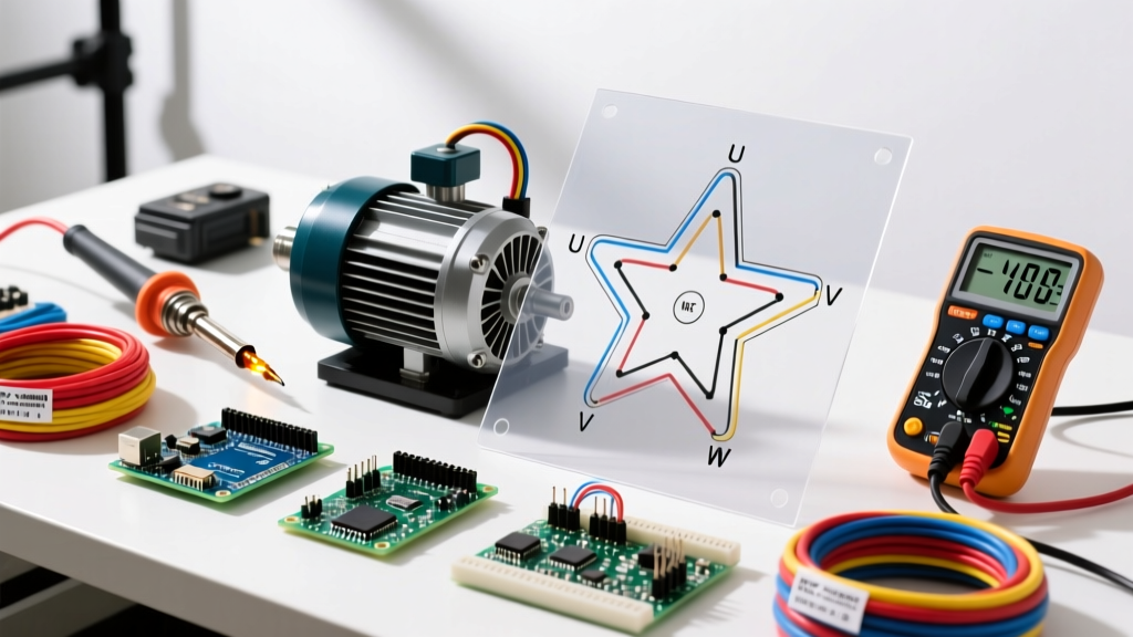
- Star-Delta (Wye-Delta): Reduces starting current to roughly 33% of DOL. Requires a motor with at least 6 accessible winding leads (U1, V1, W1, U2, V2, W2) and three separate contactors (Main, Star, Delta) plus a timer relay. Wiring complexity increases significantly, but it remains a robust, cost-effective alternative to VFDs for high-inertia loads like large exhaust fans.
- Variable Frequency Drive (VFD): The 2026 industry standard for energy efficiency and precise control. A VFD like the Yaskawa GA800 (approx. $1,450 for a 15 HP model) provides soft starting, eliminating mechanical stress. However, VFDs require specific wiring considerations, including shielded symmetrical ground cables (e.g., Belden 29402) to mitigate high-frequency dV/dt common-mode currents that can cause motor bearing fluting.
Expert Planning Tip: If your installation plan specifies a VFD, never route the VFD output cables (T1, T2, T3) in the same conduit as the 120V/24V control signal wires. The high-frequency PWM switching noise will induce ghost voltages in your control circuits, causing PLC faults and erratic sensor readings. Maintain a minimum 12-inch separation or use grounded metal dividers in cable trays.
Component Selection: Contactors and Overloads
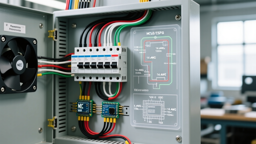
When planning a DOL or Star-Delta panel, component coordination is critical. For a 15 HP (21A) motor, a highly reliable choice is the Schneider Electric TeSys Deca line. Specifically, the LC1D25 contactor (rated 25A at 460V AC-3) paired with an LRD22 electronic overload relay (16-24A adjustment range).
Electronic overloads are vastly superior to legacy bimetallic strips in modern installations. They offer built-in single-phase loss protection (phase unbalance detection) and ground-fault monitoring, which are essential for preventing catastrophic winding burnouts in harsh industrial environments.
Control Circuit Wiring Strategies
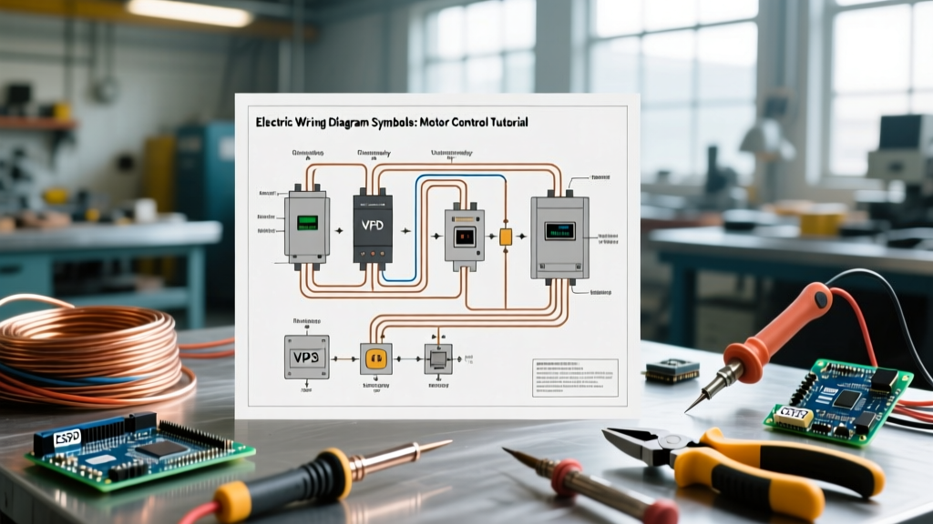
The power circuit (L1, L2, L3 to U, V, W) is only half the battle. The control circuit dictates how the motor is commanded. You must decide between an AC control voltage or a DC control voltage.
- 120V AC Control: Derived from a step-down control transformer (e.g., 480V primary to 120V secondary). The secondary must be fused and grounded. This is standard for standalone panels where PLC integration is not required.
- 24V DC Control: The mandatory choice if the motor starter is integrated into an automated system controlled by a PLC (Programmable Logic Controller). A 24V DC power supply (e.g., Phoenix Contact QUINT series) powers the contactor coil (A1, A2) via PLC relay outputs or solid-state relays.
Always wire a holding contact (Normally Open auxiliary contact, typically designated 13/14) in parallel with the momentary start pushbutton to maintain the circuit once the operator releases the button. The stop button (Normally Closed, 11/12) must be wired in series before the start circuit to break the latch.
Execution: Routing, Termination, and Grounding
Physical execution requires strict attention to torque and grounding. According to NEC 250.122, the Equipment Grounding Conductor (EGC) must be sized based on the rating of the overcurrent protective device, not the motor FLA. For our 60A breaker example, a 10 AWG copper EGC is the absolute minimum, though many engineers specify 8 AWG for mechanical durability and lower impedance fault clearing.
Termination Best Practices
Motor terminals (T1, T2, T3 or U, V, W) are subjected to severe vibration. Use vibration-resistant ring terminals or ferrules. When tightening the lugs on the contactor and motor peckerhead, you must use a calibrated torque screwdriver. For a standard 10 AWG wire in a TeSys Deca contactor, the required torque is typically 1.7 N-m (15 lb-in). Under-torquing leads to high-resistance joints, localized heating, and eventual phase loss. Over-torquing strips the screw threads or crushes the copper strands, reducing the effective wire gauge.
Common Failure Modes and Edge Cases
Even with perfect planning, edge cases can derail an installation. Understanding these failure modes allows you to design preventative measures into your wiring diagram.
Single-Phasing and Voltage Unbalance
Single-phasing occurs when one of the three power lines is lost while the motor is running. The motor will continue to spin but will draw up to 200% of its FLA on the remaining two phases, rapidly destroying the windings. While modern electronic overloads catch this, you should also plan for voltage unbalance. According to the US Department of Energy's Advanced Manufacturing Office, a mere 1% voltage unbalance across the three phases can cause a 6% to 10% increase in motor operating temperature. If your facility has heavy single-phase loads (like large welders) on the same bus, plan to install a phase-monitoring relay (e.g., Macromatic ASP-600-V) wired into the control circuit to prevent the motor from starting under unbalanced conditions.
Long Cable Runs and Voltage Drop
NEC recommends a maximum 5% voltage drop for combined feeder and branch circuits, but motor starting requires stricter limits. A 15 HP motor located 400 feet from the MCC (Motor Control Center) will experience significant voltage drop during the high-inrush DOL startup. If the voltage at the motor terminals drops below 85% of nominal during startup, the contactor coil may chatter or drop out, and the motor may stall and burn up. In long-run scenarios, you must upsize the conductors (e.g., moving from 10 AWG to 6 AWG) or switch to a VFD, which limits inrush current to 110%-150% of FLA, virtually eliminating starting voltage drop issues.
Authoritative References
For continuous professional development and code compliance verification, consult the following primary resources:
- National Fire Protection Association (NFPA): Review the latest updates to Article 430 of the National Electrical Code for legally binding installation requirements.
- US Department of Energy (DOE): Access the Motor Systems portal for whitepapers on efficiency standards, VFD integration, and predictive maintenance wiring.
- NEMA Standards: Refer to NEMA MG-1 for definitive guidelines on motor terminal markings, voltage unbalance tolerances, and enclosure classifications.