
Introduction to Dual Element 240V Water Heater Systems
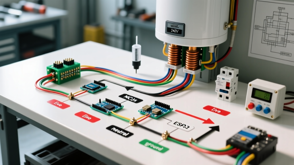
Wiring a residential electric water heater requires a precise understanding of high-voltage appliance circuits. The standard dual element 240V electric water heater wiring diagram governs how power is distributed between the upper and lower heating elements to maximize recovery time without overloading your home's electrical panel. In 2026, with the average cost of a professional plumber-electrician team exceeding $350 per hour for appliance hookups, understanding this diagram is essential for DIYers and junior technicians alike.
Most 40-gallon to 50-gallon residential tanks (such as the Rheem PROE50 T2 RH37D or Bradford White RE2H50S6) utilize two 4500-watt elements. Because running both simultaneously would draw nearly 38 amps, manufacturers use a sequential (non-simultaneous) wiring logic. This guide breaks down the exact terminal routing, NEC-compliant wire sizing, and critical failure modes you must avoid during installation.
⚠ Critical Safety Warning: 240V Lethality
A 240V circuit carries enough amperage to cause fatal ventricular fibrillation. Before opening any junction box or thermostat cover, turn off the dedicated double-pole breaker at the main service panel. Verify the absence of voltage using a CAT III or CAT IV rated multimeter (like the Fluke 117) or a non-contact voltage tester across both Line 1 and Line 2 terminals. Never assume a circuit is dead based solely on the breaker position.
Simultaneous vs. Non-Simultaneous Operation
When studying a dual element 240V electric water heater wiring diagram, you will encounter two distinct operational modes. Understanding the difference dictates your breaker and wire gauge selection.
| Feature | Non-Simultaneous (Sequential) | Simultaneous |
|---|---|---|
| Operation Logic | Only one element heats at a time. Upper element has priority. | Both elements heat at the exact same time. |
| Max Amp Draw | ~18.75 Amps (based on 4500W / 240V) | ~37.5 Amps (based on 9000W / 240V) |
| Standard Breaker | 30-Amp Double Pole | 50-Amp Double Pole |
| Wire Gauge (Copper) | 10 AWG | 6 AWG |
| Common Application | 95% of Residential Homes (Standard 40-50 Gal Tanks) | Commercial, Point-of-Use, or High-Recovery Custom Setups |
According to the U.S. Department of Energy, non-simultaneous systems are the standard for residential efficiency, as the upper element handles the immediate demand for hot water at the top of the tank, while the lower element maintains the bulk temperature during standby periods.
Component Breakdown & Terminal Identification
To wire the system correctly, you must understand the terminal layout on standard replacement thermostats, such as the widely used Camco 07863 (Upper) and Camco 07873 (Lower).
The Upper Thermostat (The Brain)
The upper thermostat houses the Emergency Cut Off (ECO) reset button and controls the transfer of power. It features five main terminals:
- L1 & L3: Power input from the main breaker panel.
- L2: Power output to the upper heating element.
- L4: Switched power output to the lower thermostat (only live when the upper tank temperature is satisfied).
- T2: Continuous power output to the lower thermostat.
The Lower Thermostat (The Workhorse)
The lower thermostat is simpler and lacks an ECO reset. It features three terminals:
- L1: Switched power input from the upper thermostat (L4).
- L3: Continuous power input from the upper thermostat (T2).
- L2: Power output to the lower heating element.
Step-by-Step Wiring Guide (Non-Simultaneous 4500W Setup)
Follow this sequence to wire a standard 10/2 NM-B (Romex) cable to a dual-element tank. Ensure your 10 AWG copper conductors are stripped to exactly 3/4 inch to prevent exposed copper outside the terminal blocks.
- Route and Secure the Cable: Feed the 10/2 NM-B cable through the tank's top junction box clamp. Tighten the clamp to secure the sheathing, not the individual wires.
- Ground the Tank: Attach the bare copper ground wire to the green grounding screw on the tank's metal junction box or the designated ground terminal on the upper thermostat. This is critical for fault-clearing per NFPA 70 (National Electrical Code) Article 250.
- Identify Line 2: Wrap the white neutral wire with black electrical tape or use a black marker at both the panel and the water heater to indicate it is being used as a hot conductor (Line 2), per NEC 200.7(C) exceptions for 240V-only circuits.
- Connect Upper Power Inputs: Connect the black wire (Line 1) to the Upper Thermostat L1 terminal. Connect the taped white wire (Line 2) to the Upper Thermostat L3 terminal.
- Wire the Upper Element: Run a jumper wire from the Upper Thermostat L2 terminal to the left screw terminal on the upper heating element.
- Route Power to the Lower Thermostat: Connect a jumper from Upper L4 to Lower L1. Connect a second jumper from Upper T2 to Lower L3.
- Wire the Lower Element: Run a wire from the Lower Thermostat L2 terminal to the left screw terminal on the lower heating element.
- Complete the Circuit (The Neutral Jumper): Connect a jumper wire between the right screw terminal of the upper element and the right screw terminal of the lower element. This completes the 240V return path for both elements.
Sizing Breakers and Wire Gauge (NEC Compliance)
Sizing your overcurrent protection correctly prevents nuisance tripping and fire hazards. The NEC requires continuous loads (those operating for 3 hours or more) to be sized at 125% of the maximum draw. While a water heater is technically a non-continuous load under some interpretations, modern electrical inspectors and best practices heavily favor the 125% rule for thermal headroom in 2026.
| Element Wattage | Voltage | Base Amp Draw | 125% Sizing Rule | Min. Copper Wire | Standard Breaker |
|---|---|---|---|---|---|
| 3500W | 240V | 14.5A | 18.1A | 12 AWG | 20A Double-Pole |
| 4500W | 240V | 18.75A | 23.4A | 10 AWG | 30A Double-Pole |
| 5500W | 240V | 22.9A | 28.6A | 10 AWG (8 AWG preferred) | 30A or 40A Double-Pole |
Note: If you are upgrading an older 4500W tank to 5500W elements for faster recovery, verify that your existing 10 AWG wire run is not bundled with other cables in a hot attic, which may require derating to 8 AWG.
Troubleshooting Common Wiring & Element Failures
Even with a perfect dual element 240V electric water heater wiring diagram execution, components can fail. Here is how to diagnose the most common edge cases:
1. The "Dry Fire" Burnout
Symptom: Brand new elements fail within seconds of turning on the power. Cause: Power was applied before the tank was 100% full of water. The elements rely on water for thermal dissipation. In the air, a 4500W element reaches melting temperatures in under 15 seconds. Fix: Always open a hot water faucet in the house and let it run until a steady stream (no air sputtering) flows before energizing the breaker. Replace both elements; the internal zinc/copper alloy will be visibly blistered or snapped.
2. Welded Contactor & ECO Tripping
Symptom: The red reset button on the upper thermostat keeps popping, or the water is dangerously hot (exceeding 180°F). Cause: The internal bimetallic switch in the upper thermostat has welded itself in the "closed" position due to arcing. The upper element heats continuously, bypassing the thermostat logic, until the ECO safety limit trips. Fix: Do not just reset the button. You must replace the upper thermostat (and ideally the lower one as a matched set). Inspect the wire terminals for heat discoloration; if the spade connectors are melted, cut them back and crimp on new high-temperature 10 AWG female disconnects.
3. 120V Miswiring (The "Lukewarm" Problem)
Symptom: Water heats, but takes 4 times longer and never reaches the target 120°F. Cause: The heater was wired to a single-pole 120V breaker, or one leg of the 240V circuit is dead (tripped half of a tandem breaker). Fix: A 240V element operating on 120V produces only 25% of its rated wattage (a 4500W element will act like an 1125W element). Test across L1 and L2 at the thermostat with a multimeter; you must read between 235V and 245V.
Expert Diagnostic Tip: When testing element continuity, isolate the element first. Disconnect the wires from the element screws. Set your multimeter to Ohms (Ω). A healthy 4500W 240V element should read between 12.5 and 13.0 Ohms. If it reads 'OL' (Open Line), the internal wire is broken and the element is dead. Check for continuity between either screw terminal and the metal tank casing; any reading other than 'OL' indicates a grounded element, which will instantly trip a GFCI or standard breaker.