
The Anatomy of the 7-Way RV Blade Connector
When towing travel trailers, fifth wheels, or heavy car haulers, the 7-way RV blade connector is the undisputed industry standard. Understanding the 7 wiring diagram for trailer setups is critical for ensuring your electric brakes, running lights, and battery charge lines function safely on the highway. While smaller utility trailers might get by with a basic 4-way flat connector, any trailer equipped with electric brakes or a breakaway switch requires the robust 7-pin configuration.
In this comprehensive vehicle-specific guide, we break down the exact pinout, address the most common factory wiring failures, and provide a heavy-duty rewiring protocol to eliminate voltage drop. According to the RV Industry Association, proper electrical integration between the tow vehicle and the trailer is one of the top factors in preventing highway towing incidents.
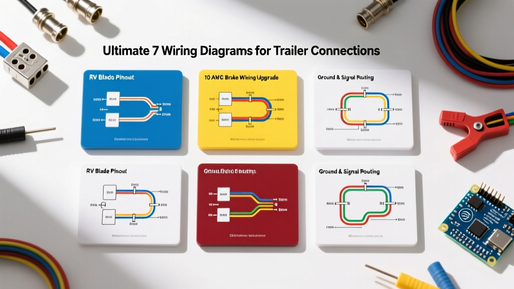
Standard 7-Way RV Blade Pinout Chart
The standard 7-way connector (often referred to as the RV blade) follows a strict color-code and pin-assignment protocol. Below is the definitive reference chart for wiring your trailer plug. Note that while colors are standardized by the SAE, some older or custom-built trailers may deviate. Always test with a multimeter before finalizing connections.
| Pin Position | Function | Standard Wire Color | Minimum Wire Gauge |
|---|---|---|---|
| 1 (Top Center) | Ground (Chassis) | White | 10 AWG (8 AWG preferred) |
| 2 (Top Right) | Electric Brakes | Blue | 10 AWG |
| 3 (Bottom Right) | Tail / Running Lights | Brown | 12 AWG |
| 4 (Center Left) | Left Turn / Stop | Yellow | 12 AWG |
| 5 (Center Right) | 12V Auxiliary / Battery Charge | Black (or Red) | 10 AWG |
| 6 (Bottom Left) | Right Turn / Stop | Green | 12 AWG |
| 7 (Bottom Center) | Auxiliary / Reverse Lights | Purple | 12 AWG |
The Voltage Drop Problem: Why Factory Wiring Fails
The most frequent complaint we see in the shop regarding the 7 wiring diagram for trailer hitches is weak electric braking performance. This is rarely a fault of the brake controller itself; rather, it is a failure of wire gauge selection over long distances.
The 12 AWG Trap
Many OEM tow packages and budget aftermarket wiring harnesses use 12 AWG wire for the electric brake circuit (Pin 2) and the 12V charge line (Pin 5). While 12 AWG is perfectly adequate for LED tail lights drawing minimal current, it is dangerously undersized for electric brakes.
Electric brake magnets can draw up to 3.5 amps per wheel. On a dual-axle trailer, that is a combined draw of 14 amps. When you run 12 AWG wire over a 25-foot distance from the tow vehicle's brake controller to the trailer axles, you experience significant voltage drop. By the time the current reaches the brake magnets, the voltage may have dropped from 12V to 9V or lower, resulting in sluggish, unpredictable braking.
Expert Rule of Thumb: Always upgrade the Ground (Pin 1), Electric Brakes (Pin 2), and 12V Charge (Pin 5) circuits to 10 AWG wire. For trailers exceeding 30 feet in length, step up to 8 AWG for the brake and ground circuits to ensure zero voltage drop under maximum load.
Step-by-Step Heavy-Duty Rewiring Guide
If you are building a custom harness or repairing a degraded one, follow this professional-grade routing procedure. We recommend using a heavy-duty molded plug like the Bargman 50-87-009 (typically priced around $22 to $28), which features thick, molded prongs that resist bending and corrosion.
- Prep the Harness: Strip back 3 inches of the outer jacket on your 7-conductor trailer cable. Slide a piece of heat-shrink tubing over the main bundle before stripping the individual wires.
- Terminate the Plug: Insert the wires into the Bargman plug according to the pinout chart above. Use a high-quality ratcheting crimp tool for the spade terminals. Do not rely on twist-on wire nuts or electrical tape inside the plug housing.
- Apply Dielectric Grease: Before sealing the plug housing, pack the internal connections with Permatex 22058 Dielectric Tune-Up Grease. This prevents moisture ingress and stops galvanic corrosion between the copper wire and brass terminals.
- Route and Secure: Run the harness along the trailer frame, securing it every 12 inches with UV-resistant nylon zip ties. Keep the wiring at least 4 inches away from the exhaust system and moving suspension components.
- Install the Breakaway Switch: Wire the breakaway switch directly to the 12V auxiliary pin (Pin 5) and the trailer's dedicated breakaway battery. Never wire the breakaway switch through the tow vehicle's charge line, as a disconnect would render the emergency brakes useless.
Modern Vehicle Integration: PWM and Smart Controllers
As of 2026, modern heavy-duty trucks from Ford, Ram, and GM utilize advanced Pulse Width Modulation (PWM) for their integrated trailer brake controllers. Unlike older time-delayed or basic proportional controllers, PWM controllers send high-frequency voltage pulses to the trailer brakes, allowing for incredibly smooth, micro-adjustable braking force.
However, this introduces a new edge case in the 7 wiring diagram for trailer setups: LED interference. Because PWM rapidly switches the voltage on and off, it can sometimes cause sensitive LED trailer marker lights to flicker if the ground circuit is compromised. To solve this, ensure your ground wire (Pin 1) is bolted directly to a clean, bare-metal section of the trailer tongue using a star washer, and apply anti-corrosion compound to the bolt threads.
Adapting for Older Trailers
If your tow vehicle has a 7-way receptacle but you are towing a lightweight utility trailer with a 4-way flat plug, do not attempt to splice the wires manually. Use a dedicated adapter like the Curt 57672 7-Way to 4-Way Flat Adapter (approx. $18). This adapter safely isolates the unused brake and charge circuits, preventing short circuits inside your vehicle's under-hood fuse box.
Common Failure Modes & Troubleshooting
Even with a perfect 7 wiring diagram for trailer connections, environmental factors and wear can cause issues. Here is how to diagnose the three most common failures:
- Symptom: Running lights work, but turn signals hyper-flash or brake lights dim when headlights are on.
Diagnosis: Ground loop or high-resistance ground. The current from the tail lights is back-feeding through the turn signal circuit because the main white ground wire has corroded. Fix: Run a dedicated 10 AWG ground wire from the trailer tongue directly to the tow vehicle's chassis, bypassing the hitch ball entirely. - Symptom: Trailer battery is dead after a long drive.
Diagnosis: Blown charge line fuse or undersized wiring. Check the tow vehicle's under-hood fuse box. Most manufacturers use a 30A or 40A fuse for the 12V charge pin. If the fuse is intact, check for voltage drop at Pin 5 while the engine is running. You should see 13.8V to 14.4V. - Symptom: Electric brakes lock up randomly or do not engage at all.
Diagnosis: Short in the blue brake wire or a failed brake controller. Disconnect the trailer and test the blue wire at the vehicle's 7-way receptacle with a multimeter. It should read 0V when the brake pedal is released. If it reads 12V, the brake controller is faulty or the wiring is shorted to the 12V charge line inside the plug housing.
Frequently Asked Questions
Can I use 14 AWG wire for the lighting circuits?
While 14 AWG might handle the amperage of modern LED trailer lights, it lacks the physical tensile strength to withstand the vibration and flexing of a trailer tongue. The National Highway Traffic Safety Administration recommends using a minimum of 12 AWG for all exterior trailer lighting circuits to prevent copper strand breakage over time.
What is the purple wire used for on a 7-way plug?
The purple wire (Pin 7) is typically reserved for auxiliary power. On boat trailers, it is often wired to a reverse lockout solenoid for surge brakes. On RVs, it can be used for backup lights or an auxiliary 12V accessory. If your trailer does not require it, cap the purple wire securely with a heat-shrink butt connector.
How often should I clean the 7-way connector?
You should inspect and clean the 7-way RV blade connector at least twice a year, or before every long towing trip. Use a specialized electrical contact cleaner to remove oxidation from the brass pins, followed by a light application of dielectric grease. According to Curt Manufacturing, routine maintenance of the plug housing prevents 80% of all trailer lighting and braking faults.