
The Critical Role of an Electric Fence Wiring Schematic
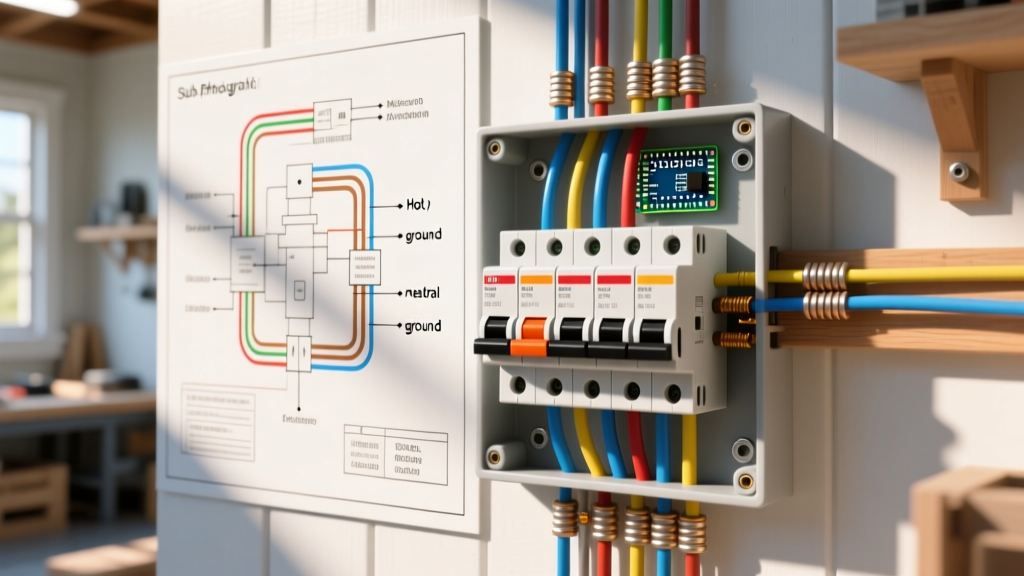
Setting up a multi-zone agricultural, livestock, or security perimeter requires far more than simply stringing wire and plugging in an energizer. A professional electric fence wiring schematic acts as the central nervous system blueprint for your entire installation. It dictates current flow, impedance matching, fault isolation, and voltage equalization across vast distances. Without a properly drafted schematic, installers frequently encounter severe voltage drops at the far end of the run, energizer burnout from lightning strikes, and untraceable short circuits.
As of 2026, with the rise of smart, IoT-connected energizers like the Gallagher i Series and advanced solar models from Parmak, your wiring schematic must also account for digital monitoring nodes and remote fault-finding sensors. This installation planning guide will walk you through designing, interpreting, and executing a robust electric fence wiring schematic that guarantees a minimum of 5,000 volts at the furthest point of your perimeter.
Deconstructing Schematic Topology: Radial vs. Loop Designs
When drafting your electric fence wiring schematic, the first decision is the conductor topology. Novice installers often default to a simple continuous loop. However, for any perimeter exceeding one mile in total wire length, a loop creates unequal resistance paths, leading to voltage lag and phase cancellation when the pulse meets itself.
The Superior 'Radial with Jumper' Layout
According to fencing standards outlined by the USDA NRCS Fence Standards, the most efficient schematic layout for large properties is the radial design with end-of-line jumpers. In this layout:
- Radial Feeds: The main hot wire runs from the energizer to the furthest point of the fence line without looping back.
- Cross-Jumpers: At the far end, a heavy-gauge jumper wire connects the main line to any parallel return wires or secondary zones.
- Result: The pulse travels down a single, low-resistance path and equalizes at the end, eliminating the 'pulse collision' voltage drop seen in continuous loops.
The Grounding Array: Your Schematic's Most Vital Component
Industry data consistently shows that over 60% of all electric fence failures stem from inadequate grounding. The earth itself is the return wire in your circuit. If your schematic does not detail a comprehensive ground bed, the system will fail, especially in dry or rocky soil conditions.
Sizing the Ground Bed
A standard rule of thumb for modern low-impedance energizers is 3 feet of ground rod per joule of output. For a 36-joule energizer (such as the Gallagher M3600i), your schematic must call for a minimum of three 10-foot ground rods. However, for optimal 2026 performance in high-resistance soils, we recommend oversizing the array to five or six rods.
CRITICAL WARNING: Galvanic Corrosion
Never mix copper and galvanized steel in your grounding schematic. Using copper wire to connect galvanized steel ground rods creates a galvanic reaction that will corrode the steel rod within a single season, rendering your ground bed useless. Always use galvanized steel wire (or specialized alloy clamps) with galvanized rods, or use pure copper rods with copper wire.
For detailed soil-resistance mitigation, the Gallagher Knowledge Center recommends driving rods at least 10 feet apart and connecting them with a continuous, unspliced galvanized ground wire using heavy-duty clamp connectors.
Conductor Selection Matrix for Your Schematic
Your electric fence wiring schematic must specify the exact conductor material and gauge for each zone. Using the wrong wire type for a specific run length will result in unacceptable resistance (Ohms/mile), bleeding off your voltage before it reaches the animal or intruder.
| Conductor Type | Gauge / Spec | Resistance (Ohms/mile) | Max Recommended Run | 2026 Avg. Cost (per 4,000 ft) |
|---|---|---|---|---|
| High-Tensile Steel | 12.5 AWG (Class 3) | ~20 Ω | 20+ miles | $75 - $95 |
| Galvanized Steel | 14 AWG | ~45 Ω | 5 - 8 miles | $55 - $70 |
| Polywire (Standard) | 6-strand stainless | ~650 Ω | 0.5 - 1 mile | $35 - $50 |
| Polytape (Visibility) | 9-strand tinned copper | ~120 Ω | 2 - 3 miles | $60 - $85 |
Note: For long-run agricultural perimeters, 12.5-gauge high-tensile wire is the undisputed standard. It provides the lowest resistance and doubles as a physical barrier when tensioned to 250 lbs using in-line strainers.
Zoning, Cut-Outs, and Lightning Protection
A professional schematic includes logical fault-isolation zones. If a tree branch falls on Zone 3, you do not want the entire 10-mile perimeter to lose power. Furthermore, the University of Minnesota Extension emphasizes the necessity of lightning diversion in regions prone to severe electrical storms.
Integrating Fault-Finding Switches
Map out your schematic with in-line cut-out switches (e.g., Gallagher G6430) at every major branch or gate. This allows you to isolate specific paddocks or perimeter sections during troubleshooting. On your drawing, represent these as standard SPST (Single Pole Single Throw) switch symbols.
Lightning Diverter Placement
Lightning strikes to the fence wire can travel back to the energizer, frying the internal motherboard. Your schematic must include a lightning diverter (choke coil and spark gap) installed on the hot wire before it enters the energizer, with a dedicated ground rod placed at least 30 feet away from the main energizer ground bed. This prevents the lightning surge from arcing through the soil into your main electronics.
Step-by-Step Execution from Schematic to Reality
Once your electric fence wiring schematic is finalized, follow this sequential installation flow to ensure the physical build matches the electrical design:
- Energizer & Main Ground Placement: Mount the energizer in a ventilated, weatherproof enclosure. Install the main ground bed first, driving 10-foot rods 10 feet apart, and connect them with continuous galvanized wire.
- Lightning Diverter Install: Install the diverter coil on the main hot feed wire, routing its ground wire to a dedicated, isolated ground rod 30+ feet away.
- Corner Post Bracing: Construct H-brace corner posts. The physical tension of high-tensile wire can exceed 1,000 lbs per wire; improper bracing will pull posts out of the ground.
- Stringing and Tensioning: Unspool the conductor, keeping it free of kinks. Use a ratchet strainer at the end of the run to tension 12.5 AWG high-tensile wire to exactly 250 lbs (use a tension gauge).
- Splicing and Jumpers: Use crimped ferrule sleeves for all wire splices. Never tie knots in high-tensile wire, as the sharp bend creates a stress fracture point that will snap under winter temperature drops.
- Zoning Switches: Wire in your cut-out switches at the designated schematic nodes.
- Final Voltage Audit: Power the system and use a digital fence voltmeter to test the voltage at the energizer, the midpoint, and the absolute furthest end of the radial run. Ensure the voltage drop does not exceed 20%.
Edge Cases: Troubleshooting High-Resistance Soil
Even with a perfect schematic, environmental factors can disrupt the earth-return circuit. In sandy, rocky, or severely drought-stricken soils, the ground bed may exhibit resistance upward of 100 ohms, choking the energizer's pulse.
The Bentonite Clay Solution: If your soil resistance is too high, excavate the area around your ground rods and backfill with a slurry of sodium bentonite clay and water. Bentonite is highly conductive, retains moisture indefinitely, and swells to create a tight, low-resistance seal around the galvanized rod. This technique, widely used in commercial telecom grounding, can drop ground rod resistance from 150 ohms down to under 15 ohms, ensuring your schematic performs flawlessly in the real world.