
Why Code Compliance Matters in Trailer Braking Systems
When interpreting the wiring diagram for a Tekonsha trailer brake controller, technicians and DIYers must look beyond simple point-to-point connectivity and prioritize fail-safe redundancy. As of 2026, modern tow vehicles feature complex multiplexed electrical networks (CAN bus systems) that are highly sensitive to voltage spikes and improper grounding. A poorly executed brake controller installation doesn't just result in a blown fuse; it can lead to catastrophic brake lockup, melted harnesses, or a complete failure to stop a 5,000-pound trailer in an emergency.
Adhering to guidelines set forth by the National Highway Traffic Safety Administration (NHTSA) and the RV Industry Association (RVIA) ensures your setup meets rigorous safety benchmarks. This guide breaks down the exact wiring protocols for industry-standard models like the Tekonsha Prodigy P3 (Model 90195) and Prodigy P2 (Model 90885), focusing heavily on code compliance, wire gauge selection, and grounding integrity.
Decoding the Core Wiring Diagram
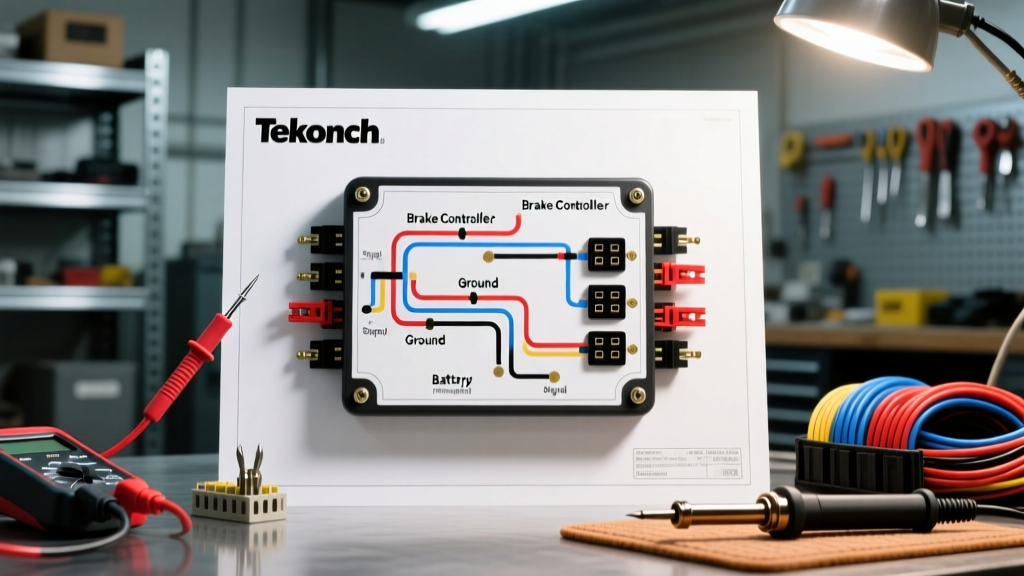
The universal wiring diagram for a Tekonsha proportional brake controller relies on a four-wire pigtail that interfaces with the tow vehicle's electrical system and the 7-way RV blade connector at the rear bumper. While the physical routing varies by vehicle make and model, the electrical logic remains constant.
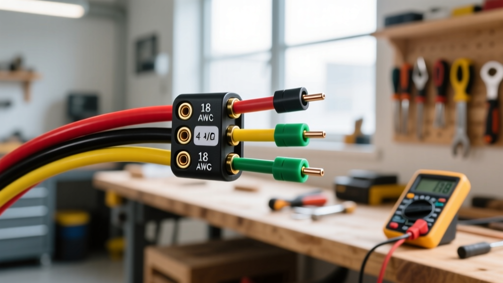
Wire Color Code and Gauge Matrix
One of the most frequent code violations in DIY installations is using undersized wire for the power and ground circuits. Voltage drop over a 15-foot harness can severely degrade the pulse-width modulation (PWM) signal sent to the trailer brakes.
| Wire Color | Function | Minimum Gauge (2-4 Brakes) | Minimum Gauge (6-8 Brakes) | Connection Point |
|---|---|---|---|---|
| Black | 12V Power Input | 12 AWG | 10 AWG | Vehicle Battery (+) via 30A Circuit Breaker |
| White | System Ground | 12 AWG | 10 AWG | Vehicle Chassis or Battery (-) |
| Red | Stoplight Switch Signal | 14 AWG | 14 AWG | Cold side of brake pedal switch |
| Blue | Brake Output to Trailer | 12 AWG | 10 AWG | 7-Way Connector (Pin 2 / 5 o'clock) |
Note: Always use stranded, SAE J1128-compliant copper wire. Solid core wire will fracture under the constant vibration of a tow vehicle chassis.
Critical Safety Mandates: Breakaway Switches & Grounding
Safety and code compliance hinge on two specific circuits that are frequently misunderstood: the breakaway switch and the primary ground.
The Breakaway Switch: A Standalone Mandate
According to Tekonsha's official technical support guidelines and federal DOT regulations, trailers equipped with electric brakes must have a breakaway system. The most dangerous mistake an installer can make is splicing the breakaway switch's power feed into the blue brake output wire or the black 12V accessory circuit.
Safety Checkpoint: The breakaway switch MUST be wired directly to the trailer's dedicated 12V battery via its own independent 20A or 30A auto-reset circuit breaker. If the trailer separates, the pin pulls, and the breakaway system applies 100% battery voltage directly to the brake magnets, independent of the tow vehicle's wiring harness.
The #1 Failure Mode: Inadequate Grounding
Over 70% of all trailer brake controller faults (such as the 'SH' or 'OL' error codes on a Prodigy P3 display) are caused by ground loop issues. Relying solely on the white ground wire inside the 7-way connector plug is a severe safety risk. Corrosion, plastic bumper isolators, and hitch ball grease can interrupt the ground path.
Code-Compliant Fix: Run a dedicated 10 AWG white ground wire from the Tekonsha controller directly to the vehicle's battery negative terminal or a known, unpainted chassis ground point within 18 inches of the battery. Do not ground the controller to the dashboard frame or steering column.
PWM vs. Rheostat: Understanding the Signal
Modern Tekonsha controllers like the Prodigy P3 utilize Pulse-Width Modulation (PWM) rather than old-school rheostat voltage dropping. A rheostat physically restricts voltage, generating massive heat and wasting energy. PWM sends rapid, full-voltage 12V pulses to the brake magnets. The inertia sensor inside the Tekonsha unit dictates the 'on' time of these pulses. Because PWM relies on high-speed switching, using undersized wire or poor crimp connections introduces resistance that alters the pulse waveform, resulting in harsh, jerky braking or delayed engagement.
Step-by-Step Fail-Safe Installation Protocol
Follow this exact sequence to ensure your wiring diagram translates into a safe, road-legal installation.
- Disconnect Vehicle Power: Remove the negative battery cable to prevent shorting the CAN bus system while routing wires through the firewall.
- Mount the Controller: The Tekonsha Prodigy series features an internal inertia sensor that MUST be mounted level, parallel to the direction of travel, and within the specified pitch/yaw tolerances outlined in the manual. Mounting it at a crooked angle will cause premature or delayed brake application.
- Route the Harness: Pass the four-wire pigtail through the firewall using an existing rubber grommet. Never drill through bare metal without a grommet; sharp edges will slice the wire insulation, causing a dead short.
- Install the Circuit Breaker: Mount a 30A auto-reset thermal circuit breaker within 6 inches of the vehicle's positive battery terminal. Connect the black wire to the 'AUX' post of the breaker.
- Splice the Red Wire: Use a T-tap or, preferably, a solder-and-heat-shrink method to connect the red wire to the 'cold' side of the brake pedal switch. Verify with a multimeter that this wire only shows 12V when the pedal is depressed.
- Terminate and Seal: Use adhesive-lined marine-grade heat shrink on all butt connectors. Apply dielectric grease to the 7-way connector pins to prevent galvanic corrosion.
Troubleshooting Voltage Drop & Code Violations
If your Tekonsha controller displays an 'OL' (Overload) or 'SH' (Short) code, do not immediately assume the controller is defective. Perform a voltage drop test.
- The Test: Set your multimeter to DC Volts. Place the positive probe on the blue output wire at the back of the controller, and the negative probe on the battery negative terminal. Have an assistant press the brake pedal (or use the manual override lever).
- The Benchmark: You should read within 0.5V of the battery's resting voltage (e.g., 12.1V on a 12.6V battery). If you read 9V or 10V, you have excessive resistance in the blue wire run or the 7-way connector.
- The Fix: Replace the blue wire with 10 AWG stranded copper and replace the 7-way connector plug. Cheap, stamped-brass connector pins are a primary source of resistance and heat buildup.
Final Compliance Thoughts
Building a safe towing rig requires respecting the physics of electricity and the legal mandates of highway safety. By strictly adhering to the proper wiring diagram for a Tekonsha trailer brake controller, utilizing 10 AWG wire for high-current circuits, and maintaining independent breakaway systems, you ensure compliance with NFPA 1192 and DOT standards. Never compromise on connection quality; a $5 investment in marine-grade heat shrink is the cheapest insurance policy you can buy for your trailer braking system.