
Why Marine Audio Wiring Demands a Different Approach
Interpreting a wiring diagram for boat stereo systems requires a fundamental shift from automotive car audio logic. In a vehicle, the steel chassis serves as a universal ground, and the environment is relatively dry. On a boat, the hull is typically fiberglass or aluminum, meaning every ground must be explicitly wired back to a central negative bus bar. Furthermore, the marine environment is saturated with saltwater, high humidity, and constant vibration, all of which accelerate galvanic corrosion and mechanical fatigue.
According to the American Boat & Yacht Council (ABYC), marine DC electrical systems must adhere to strict E-11 standards to prevent fires and equipment failure. Using automotive copper-clad aluminum (CCA) wire or standard vinyl electrical tape on a boat will inevitably lead to black-wire corrosion (copper oxidation) and voltage drops that destroy expensive amplifiers. This guide provides a comprehensive, ABYC-compliant wiring topology for modern marine audio setups, including DSP amplifiers and NMEA 2000 integrated head units.
Core Wiring Diagram for Boat Stereo Topology
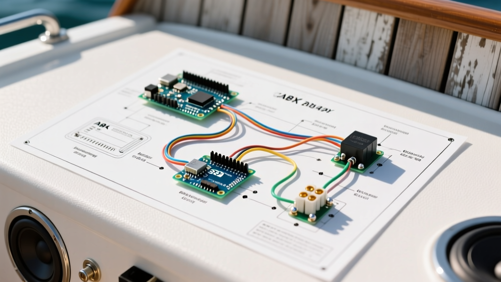
A proper marine audio system does not wire components directly to the battery terminals. Instead, it utilizes a centralized bus bar topology protected by primary and secondary overcurrent devices. Below is the logical flow of a complete marine audio wiring diagram.
1. Primary Battery Protection
The main positive battery post must be protected within 7 inches of the terminal. For a high-output audio system, install a Blue Sea Systems MRBF (Marine Rated Battery Fuse) or an ANL fuse block directly on the positive terminal. This protects the main positive feed cable in the event of a dead short against the engine block or hull.
2. The Bus Bar Distribution Center
- Positive Bus Bar: Receives the main feed from the battery (post-MRBF) and distributes power to the head unit, amplifiers, and NMEA 2000 backbone.
- Negative Bus Bar: Collects all ground wires from the audio equipment and routes them back to the battery's negative terminal via a DC shunt (for battery monitoring).
Head Unit Pinout & Low-Current Connections
Modern marine head units, such as the Fusion Apollo MS-RA70N or JL Audio MM50s, utilize standard ISO-style wiring harnesses, but the routing is critical.
| Wire Color | Function | Marine Routing Specifics |
|---|---|---|
| Yellow (B+) | Constant 12V Memory | Route to a fused port on the positive bus bar. Maintains presets and DSP tuning profiles. |
| Red (ACC) | Switched 12V Ignition | Route to an 'Accessories' breaker panel or a keyed ignition switch to prevent parasitic battery drain. |
| Black (GND) | Chassis Ground | Never ground to the engine block. Route directly to the main negative bus bar. |
| Blue (Amp Turn-On) | Remote Trigger | Connect to the amplifier's 'REM' terminal. Use 18 AWG tinned wire. |
High-Current Amplifier & Bus Bar Routing
When wiring high-wattage marine amplifiers (e.g., the JL Audio M-Series M700/5), voltage drop is the primary enemy. A 12V nominal system operates at roughly 13.8V to 14.4V when the alternator is running. The ABYC recommends a maximum voltage drop of 3% for critical electronics and audio amplifiers to prevent clipping and thermal shutdown.
For a 50-amp amplifier draw located 15 feet from the battery, the wiring diagram dictates the use of 4 AWG tinned marine-grade copper wire. The positive feed must pass through a dedicated thermal circuit breaker or an inline AGU fuse located within 7 inches of the positive bus bar connection.
ABYC Wire Gauge & Fuse Sizing Matrix
The following table provides baseline wire gauge selections based on ABYC E-11 voltage drop calculations (assuming a 3% drop at 13.8V). Always measure the total circuit length (positive + negative return) to determine the correct gauge.
| Max Current (Amps) | Total Wire Length (Feet) | Recommended Wire Gauge (AWG) | Recommended Fuse Size |
|---|---|---|---|
| 10A (Head Unit) | 10 ft | 16 AWG | 10A ATC Blade |
| 15A (Head Unit + Zone) | 15 ft | 14 AWG | 15A ATC Blade |
| 30A (Small Amp/DSP) | 20 ft | 10 AWG | 30A AGU / ANL |
| 60A (Monoblock Amp) | 15 ft | 4 AWG | 60A ANL |
| 120A (Multiple Amps) | 20 ft | 1/0 AWG | 125A Class T |
Expert Note: As of 2026, the price of pure copper has surged, leading to a flood of cheap CCA (Copper Clad Aluminum) wire on the market. CCA has 40% less conductivity than pure copper and is highly prone to snapping under marine vibration. Always verify your wire is stamped 'AWG' and 'Marine Grade' (tinned stranded copper) from manufacturers like Ancor or Pacer Group.
NMEA 2000 Integration for Modern Head Units
A complete wiring diagram for boat stereo systems in the modern era must account for digital networking. Premium head units integrate with the boat's National Marine Electronics Association (NMEA) 2000 backbone to display engine RPM, fuel flow, and depth data directly on the stereo screen.
Wiring the NMEA 2000 network requires a DeviceNet micro-cable setup. The head unit's NMEA 2000 pigtail must be connected to a T-connector on the backbone. Crucially, the backbone must be powered by a dedicated fused 12V feed and terminated at both physical ends with 120-ohm micro terminators to prevent signal reflection and data packet loss.
Termination Standards: Crimping & Heat Shrink
The most common point of failure in any marine wiring diagram is the termination point. Solder is strictly prohibited by the ABYC for marine DC wiring because it creates a brittle, solid joint that will crack under the constant harmonic vibration of a boat hull and outboard engines.
The Proper Crimp & Seal Method
- Strip the Wire: Use a precision wire stripper to avoid nicking the copper strands. Nicked strands create stress risers that lead to wire breakage.
- Select the Terminal: Use marine-grade, adhesive-lined heat shrink terminals (e.g., Ancor or 3M). The nylon insulator barrel provides strain relief, while the internal hot-melt adhesive creates a waterproof seal.
- Crimp Tool: Do not use cheap automotive crimpers. Use a dedicated ratcheting crimper designed for insulated terminals, such as the Knipex 97 53 14 or the Titan 11910. A proper crimp deforms the barrel into a hexagonal or diamond shape, creating a cold-weld gas-tight seal.
- Apply Heat: Use a heat gun (not a lighter) to shrink the insulation. Heat from the middle outward until a small bead of adhesive squeezes out of the ends, ensuring no moisture can wick into the wire strands.
Troubleshooting Common Marine Audio Failures
Even with a perfect wiring diagram for boat stereo components, environmental factors can introduce faults. Here is how to diagnose the most common marine-specific issues:
1. Amplifier Thermal Shutdown (Voltage Drop)
Symptom: The amplifier plays loudly for 5 minutes, then cuts out. The LED shifts from green to red/amber.
Diagnosis: Undersized wire or corroded bus bar lugs are causing severe voltage drop. As the amplifier demands current, the voltage at its terminals drops below 10.5V, triggering the internal protection circuit. Use a digital multimeter to measure voltage directly at the amp's B+ and GND terminals while playing bass-heavy audio. If it drops below 11.5V, upgrade the wire gauge or clean the bus bar connections with a brass wire brush and dielectric grease.
2. Parasitic Battery Drain (Memory Wire Fault)
Symptom: The starting battery is dead after the boat sits for 48 hours.
Diagnosis: The Yellow (Constant 12V) and Red (Switched 12V) wires on the head unit harness were swapped. The head unit is receiving constant power on the ignition circuit, preventing it from entering sleep mode. Verify the wiring diagram pinout and ensure the Red wire is routed through a keyed switch or the 'Accessory' bus bar that loses power when the battery selector switch is turned to 'OFF'.
3. Alternator Whine (Ground Loop)
Symptom: A high-pitched whining noise that increases in pitch with engine RPM.
Diagnosis: The head unit and the amplifier are grounded to different bus bars, or the negative bus bar has a poor connection to the battery, causing the audio signal's ground reference to fluctuate with the alternator's AC ripple. Ensure all audio component grounds terminate at a single, dedicated negative bus bar, and verify the main negative cable from the bus bar to the battery is tightly torqued and free of corrosion.
By strictly adhering to ABYC standards, utilizing tinned marine-grade copper, and implementing a centralized bus bar topology, your boat stereo wiring diagram will yield a reliable, high-fidelity audio system capable of surviving the harshest marine environments.