
Why Generic Diagrams Fail Modern Honda Diagnostics
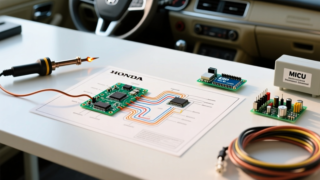
When diagnosing electrical faults in 8th through 11th generation models (2008–2026), relying on a generic, simplified schematic is a recipe for misdiagnosis. A true OEM wiring diagram for Honda Accord vehicles reveals the complex Multiplex Integrated Control Unit (MICU) networks, CAN bus topologies, and specific pinout architectures that aftermarket manuals often omit. In 2026, with dealership diagnostic fees averaging $165 to $210 per hour, mastering these diagrams is the most cost-effective way to isolate faults in your driveway.
Generic diagrams often group circuits together, hiding the fact that a single ground point (like G401 or G501) might serve both the power window multiplex and the SRS (Supplemental Restraint System) module. To access factory-accurate schematics, technicians use the official Honda TechInfo portal, which provides 48-hour access to complete service manuals and wiring routing guides for a nominal fee.
Decoding Honda’s Specific Wiring Nomenclature
Before you pick up a Digital Multimeter (DMM), you must understand how Honda labels its wires and connectors. Unlike domestic manufacturers that use numeric wire codes, Honda relies on color abbreviations and specific connector designations.
Wire Color Codes
- BLK (Black): Almost exclusively used for chassis grounds.
- BLK/WHT (Black with White Stripe): Sensor grounds or ECU-specific grounds.
- RED/WHT or RED/BLU: Switched or constant 12V power feeds.
- GRN/WHT or YEL/RED: Communication lines (like F-CAN or B-CAN bus networks).
Connector and Ground Identifiers
Connectors are labeled with a "C" followed by a number (e.g., C501 for the under-dash fuse box connector). Grounds are labeled with a "G" (e.g., G401, located behind the left kick panel). If your diagram shows a fault in the driver’s door multiplex, tracing the BLK wire to G401 is your first step. A voltage drop test across this ground should read less than 0.05V under load, a standard outlined in Fluke's official voltage drop testing guidelines.
Step-by-Step Troubleshooting: The Parasitic Battery Draw
A dead battery is the most common electrical complaint in 9th and 10th generation Accords (2013–2022). The culprit is often a module failing to enter "sleep mode." However, testing this requires a specific approach because modern Accords utilize multiple CAN networks that can take up to 20 minutes to power down.
The Parallel Shunt Method
Never simply disconnect the negative battery terminal and insert your multimeter in series. The moment you break the circuit and reconnect it, every module wakes up, resetting your 20-minute sleep timer. Instead, use the parallel shunt method:
- Turn off the ignition, remove the key fob from the vehicle's vicinity, and ensure all doors, the trunk, and the hood are latched (use a piece of tape to depress the hood latch switch so the car "thinks" it is closed).
- Connect a heavy-gauge jumper cable between the negative battery post and the disconnected negative battery clamp. This maintains circuit continuity.
- Set your DMM (such as the Fluke 87V) to the milliamp (mA) setting and connect the probes in parallel across the jumper cable.
- Remove the jumper cable. The current now flows exclusively through your multimeter without ever breaking the vehicle's electrical circuit.
- Wait 15 to 25 minutes. According to AAA's automotive battery diagnostics standards, a normal parasitic draw for a modern midsize sedan should settle below 50mA (0.05A). If it remains above 80mA, you have a rogue module.
Pro Tip: If the draw remains high, consult your wiring diagram for Honda Accord MICU fuse assignments. Pull fuses one by one for the Under-Dash and Under-Hood fuse boxes. When the amperage drops, you’ve isolated the faulty circuit (often the Bluetooth hands-free module or a failing door multiplex switch).
Common Circuit Failure Points & Symptoms
| Circuit / Component | Wiring Diagram Reference | Common Failure Mode | Symptom |
|---|---|---|---|
| Alternator LIN Wire | ECU to Alternator (GRN/RED wire) | Chafing near the radiator fan shroud | Battery light on, voltage stuck at 12.4V or spiking to 15.2V |
| MICU Power Feed | Under-Dash Fuse #19 (15A) | Corrosion on C501 connector pins | Intermittent failure of interior lights and power locks |
| Electronic Load Detector (ELD) | Under-Hood Fuse Box, 3-pin connector | Internal resistor failure or broken BLK/WHT ground | Dimming headlights at idle, erratic alternator output |
| Driver Door Multiplex | Power Window Master Switch connector | Broken wires in the door jamb boot | Passenger windows won't roll down, key fob lock fails |
Troubleshooting the Alternator and ELD Network
Honda utilizes a unique charging system controlled by the Electronic Load Detector (ELD) and the Engine Control Module (ECM). Unlike older vehicles where the alternator outputs a steady 14.2V, the Accord's ECM uses a Local Interconnect Network (LIN) wire to command the alternator to output either 12.5V (economy mode) or 14.4V (charging mode) based on electrical load and battery temperature.
If your headlights dim at idle but brighten when you rev the engine, do not immediately replace the alternator. Consult your wiring diagram to locate the ELD, usually housed inside the under-hood fuse box. Test the ELD's 3-pin connector:
- Pin 1 (BLK/WHT): Ground. Must have continuity to the chassis.
- Pin 2 (RED/BLU): 12V reference from the ECM.
- Pin 3 (GRN/RED): Signal wire to the ECM. Should vary between 1.5V and 3.5V depending on the electrical load (turn on headlights and rear defroster to see voltage change).
If the signal wire remains static, the ELD is faulty—a $45 to $65 part—saving you from unnecessarily replacing a $300 alternator.
Diagnosing F-CAN and B-CAN Bus Networks
Modern Accords rely on two primary Controller Area Network (CAN) buses: the F-CAN (Fast CAN, operating at 500 kbps) for powertrain and chassis modules, and the B-CAN (Body CAN, operating at 125 kbps) for comfort and convenience features like the HVAC and MICU. When a module fails to communicate, a generic OBD2 scanner might just show a "U-code" (e.g., U0155 - Lost Communication with Instrument Panel Cluster).
Your wiring diagram for Honda Accord CAN circuits will show the F-CAN H (typically White) and F-CAN L (typically Red) wires twisted together. To diagnose a bus crash:
- Set your DMM to DC Volts.
- Backprobe the F-CAN H and L wires at the DLC (Data Link Connector) under the driver's dash.
- With the ignition ON, F-CAN H should read approximately 2.6V to 3.5V, and F-CAN L should read 1.5V to 2.4V. The sum should be very close to 5.0V.
- If both read 0V, you have a short to ground. If both read 12V, you have a short to power. If they read exactly the same voltage (e.g., 2.5V each), the bus is offline or a module is crashing the network.
Isolating a crashed B-CAN requires unplugging modules one by one (starting with the HVAC control unit and MICU) until network communication is restored. This level of precision is only possible with the factory schematic in hand.
Essential Diagnostic Tools for the DIYer
To execute the tests outlined above, you need equipment that can handle low-voltage signal testing and high-amperage inductive clamps. Here is what professional technicians are using in 2026:
- Fluke 87V Industrial Multimeter ($420 - $450): The gold standard for automotive diagnostics. Its low-impedance (LoZ) mode prevents false readings from ghost voltages in Honda's multiplex circuits.
- Fluke i3000s AC/DC Current Clamp ($280): Essential for measuring parasitic draws without breaking the circuit, completely bypassing the need for the parallel shunt method if you prefer non-intrusive testing.
- Lisle 39970 Backprobe Pin Set ($18): Crucial for piercing the weather seals of Honda's C-series connectors without damaging the delicate copper strands, which can lead to future corrosion.
- Power Probe IV ($250): Excellent for instantly verifying 12V power and ground at the MICU connectors without needing to run a separate ground lead for your multimeter.
Frequently Asked Questions
Where can I find a free wiring diagram for Honda Accord models?
While forums like DriveAccord or HondaTech offer user-uploaded snippets, these are often incomplete or mislabeled for specific trim levels (e.g., confusing the Hybrid IMA wiring with the standard 2.4L/3.5L diagrams). For accurate troubleshooting, a 24-hour subscription to Honda TechInfo is the most reliable and cost-effective method.
Can a bad ground cause multiple unrelated electrical issues?
Yes. In the Accord, ground point G401 (left kick panel) and G501 (right kick panel) are shared by multiple MICU circuits. A loose G401 can simultaneously cause power window failure, erratic gauge cluster behavior, and SRS warning lights. Always check shared grounds before replacing expensive control modules.