
The Missing Link in High-Power E-Bike Builds
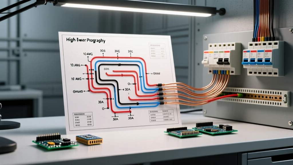
The micro-mobility landscape in 2026 has seen a massive surge in high-power custom electric bikes, with 72V systems pushing 3000W to 8000W becoming the standard for enthusiasts. However, when builders search for a standard electric bike motor wiring diagram, they are almost always presented with a simplified schematic that connects the battery directly to the motor controller. From a 'Panel & Breaker' engineering perspective, this is a catastrophic oversight. High-capacity lithium-ion packs can deliver 150+ amps of continuous current and over 400 amps during a dead short. Without a properly engineered DC breaker panel and fuse distribution block integrated into your wiring diagram, a single chafed phase wire will bypass the Battery Management System (BMS) and trigger immediate thermal runaway.
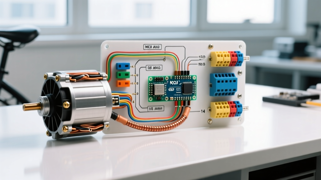
This guide bridges the gap between basic motor controller wiring and professional-grade DC electrical panel design. We will detail how to integrate DC circuit breakers, main contactors, and pre-charge circuits into your electric bike motor wiring diagram to ensure your high-power build is both performant and safe.
Why Your Wiring Diagram Needs a DC Breaker Panel
In residential AC electrical panels, breakers protect the wiring from exceeding its thermal limits. The exact same principle applies to the DC side of an electric vehicle. The BMS inside your battery pack is designed to manage cell balancing and handle minor over-current events, but it is not a primary short-circuit protection device. Solid-state MOSFETs inside a BMS can fail closed during a massive current spike.
The Catastrophic Failure Mode: Unfused 72V Systems
Consider a custom build using a 72V 40Ah battery and a Kelly KLS-7230H controller. If the 2 AWG positive battery cable rubs against the steel swingarm, it creates a dead short. The battery will attempt to dump its entire C-rating into the short. Without a physical DC breaker or Class-T fuse positioned within 7 inches of the battery positive terminal, the wire insulation will melt, igniting the surrounding components. According to safety guidelines outlined in NFPA 855 regarding stationary and mobile energy storage systems, overcurrent protection must be located as close to the power source as practically possible to minimize the length of unprotected conductors.
Core Components: DC Breakers, Fuse Blocks, and Wire Gauges
Selecting the right breaker requires understanding the difference between thermal and magnetic trip curves. Standard automotive circuit breakers use a bi-metallic strip (thermal) which reacts too slowly to a dead short, or a simple magnetic coil that might nuisance-trip during the massive inrush current of motor startup. For an electric bike motor wiring diagram, you need a Hydraulic-Magnetic DC Breaker or a Class-T Limitron Fuse.
Expert Insight: Never use standard AC residential breakers (like Square D Homeline) on a 72V DC e-bike system. AC breakers rely on the alternating current's zero-crossing point to extinguish the electrical arc when the contacts open. In a 72V DC system (which peaks at 84V fully charged), an AC breaker will fail to extinguish the arc, resulting in the breaker welding itself shut or catching fire. Always use DC-rated components with proper arc chutes.
72V System Breaker & Wire Sizing Matrix
| Motor Wattage | Peak Controller Current | Recommended DC Breaker / Fuse | Main Wire Gauge (AWG) | Phase Wire Gauge (AWG) |
|---|---|---|---|---|
| 1500W - 2000W | 60A - 90A | 80A DC Breaker (e.g., Blue Sea C-Series) | 6 AWG Silicone | 8 AWG Silicone |
| 3000W | 120A - 150A | 150A Class-T Fuse (Bussmann ANN-150) | 2 AWG Silicone | 4 AWG Silicone |
| 5000W - 8000W | 200A - 300A | 250A Class-T Fuse + 250A Main Contactor | 1/0 AWG Silicone | 2 AWG Silicone |
Note: Wire ampacity is based on high-strand-count silicone insulation rated for 200°C. Standard PVC THHN wire will melt under the high-frequency heat generated by motor controller phase outputs. For baseline copper ampacity standards, refer to industry wire ampacity charts, but always apply a 20% derating factor for the enclosed, high-ambient-heat environment of an e-bike battery bag.
Step-by-Step: Integrating the Breaker Panel into the Motor Wiring Diagram
To properly upgrade your electric bike motor wiring diagram, follow this sequential integration flow. This setup assumes a 72V system utilizing a Kelly KLS-series controller and a QS Motor hub drive.
- Battery to Main DC Breaker: Crimp a heavy-duty ring terminal onto the positive output of your battery's XT90 or Anderson SB175 connector. Route this directly to the input stud of your DC breaker or Class-T fuse block. This cable must be less than 7 inches long. Secure it with adhesive-lined heat shrink to prevent moisture ingress.
- The Pre-Charge Circuit (Critical): High-power controllers feature massive capacitor banks on their DC input. If you connect a fully charged 84V battery directly to the controller, the inrush current can exceed 500A for a few milliseconds, welding your main contactor or destroying the controller's internal capacitors. Wire a 10W 100-ohm pre-charge resistor in parallel with a momentary push-button switch, bypassing the main contactor. Press the button for 2 seconds to slowly charge the capacitors before engaging the main DC breaker.
- Breaker to Controller B+ and B-: Route the protected positive DC line from the breaker output to the controller's B+ (Battery Positive) terminal. Connect the negative line directly from the battery's negative terminal to the controller's B- terminal. Use a 500A/50mV DC shunt on the negative line if you are integrating a digital battery monitor (like a Victron SmartShunt) to track precise amp-hours consumed by the motor.
- Phase Wires (U, V, W): Connect the three thick phase wires from the controller to the motor. In high-power builds, the stock motor phase wires are often too thin. Cut them back and solder 4 AWG high-strand silicone wire directly to the motor stator windings. Ensure the hall sensor wires are routed on the opposite side of the swingarm from the phase wires to prevent electromagnetic interference (EMI).
- Hall Sensors & Throttle Integration: Wire the 5-pin hall sensor connector and the 3-pin throttle connector to the controller's low-voltage harness. Protect this low-voltage harness with a secondary 5A mini blade fuse connected to the DC-DC converter's 12V output.
Real-World Component Selection & Pricing (2026 Market)
Building a reliable DC breaker panel for your e-bike requires investing in marine or EV-grade components. Cheap Amazon alternatives often use copper-plated aluminum internals which oxidize and create high-resistance hot spots.
- Blue Sea Systems C-Series 150A DC Breaker: Priced around $85 in 2026. Features a hydraulic-magnetic trip curve specifically designed to ignore the millisecond inrush spikes of motor controllers while tripping instantly on a sustained short circuit. Refer to Blue Sea's circuit protection engineering guides for detailed trip curve graphs.
- Bussmann ANN-150 Class-T Fuse & Block: Priced at $45 for the set. Class-T fuses offer an interrupting capacity of 20,000 amps at 125VDC, far exceeding the short-circuit potential of a standard 72V e-bike pack.
- Albright SW200 Main Contactor: Priced around $110. Used in conjunction with the pre-charge circuit to physically disconnect the high-current DC lines when the bike is keyed off.
- 2 AWG Silicone Wire (per foot): Expect to pay $3.50 to $5.00 per foot for genuine 1000+ strand tinned copper silicone wire. Avoid 'CCA' (Copper Clad Aluminum) wire sold on budget marketplaces.
Troubleshooting Common Breaker & Controller Faults
Even with a perfect electric bike motor wiring diagram, real-world variables can cause electrical faults. Here is how to diagnose the most common panel and breaker issues.
Nuisance Tripping vs. True Short Circuit
If your main DC breaker trips only when you accelerate hard from a dead stop, but holds fine during cruising, you are experiencing nuisance tripping due to peak current draw. A 3000W motor at 72V draws roughly 41 amps continuously, but the Kelly controller may pull 120A peak to generate starting torque. Solution: Check your controller's 'Battery Current Limit' setting in the software. Lower it by 10% increments until it aligns with your breaker's continuous rating, or upgrade to a higher-amperage Class-T fuse setup.
Hall Sensor Burnout
If your motor stutters, makes a loud grinding noise, and the controller throws an Error Code 04 (Hall Fault), your low-voltage wiring has likely been compromised. In many DIY builds, the 5V hall sensor wires are routed too close to the 72V phase wires. The massive electromagnetic field generated during acceleration induces a voltage spike in the hall wires, frying the 5V logic board inside the controller. Solution: Always use shielded twisted-pair cable for hall sensors, and ground the shield mesh at the controller end only to prevent ground loops.
Conclusion & Safety Standards
Treating your high-power e-bike like a toy rather than a light electric vehicle is a recipe for disaster. By upgrading your standard electric bike motor wiring diagram to include a dedicated DC breaker panel, main contactor, and pre-charge circuit, you elevate your build from a fire hazard to a reliable, road-worthy machine. Always adhere to EV safety testing standards, such as those outlined in SAE J2464 for RESS Safety, which emphasize robust overcurrent protection and thermal management. Invest in marine-grade DC breakers, use high-strand silicone wiring, and never bypass your fuses to chase a few extra amps of performance.