
Decoding the Ford 3000 Electrical Wiring Diagram
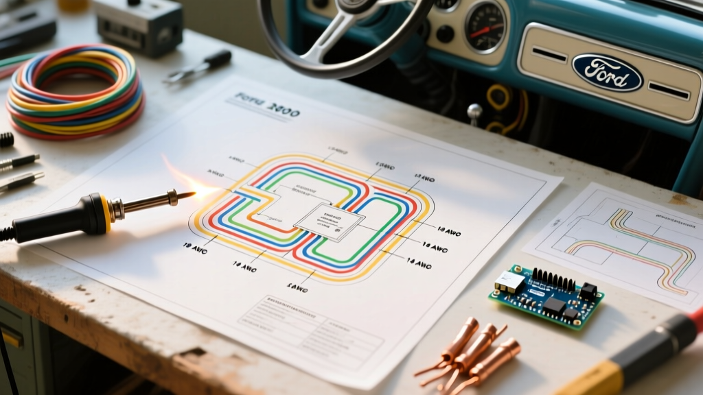
Restoring the electrical system of a 1965–1975 Ford 3000 tractor requires the same meticulous attention to detail as wiring a high-draw industrial appliance. The factory Ford 3000 electrical wiring diagram is the foundational blueprint for this 12-volt, negative-ground system. Whether you are dealing with a battered original harness or a patchwork of previous repairs, understanding the schematic is critical for preventing voltage drops, component failure, and catastrophic electrical fires.
Unlike modern CAN-bus systems, the Ford 3000 relies on a straightforward point-to-point analog wiring architecture. However, agricultural environments introduce severe variables: extreme vibration, moisture, diesel soot, and high ambient heat. According to the SAE J1128 Standard for low-tension primary cable, wiring in engine compartments must withstand temperatures up to 125°C and resist degradation from oils and solvents. Standard hardware-store thermoplastic wire will melt and short out against the Ford 3000's exhaust manifold within a single season.
Generator vs. Alternator Configurations
The most common point of confusion when reading the Ford 3000 electrical wiring diagram is the charging system. Early production models (1965–1969) utilized a Ford-built generator paired with a mechanical voltage regulator. Later models transitioned to the Motorola alternator.
Critical Safety Warning: If your tractor has been converted from a generator to a 1-wire alternator, the original 4-terminal mechanical voltage regulator MUST be completely bypassed. Leaving the old regulator wired into the harness while using an internally regulated alternator will cause the alternator to overcharge, boiling the battery acid and potentially melting the 10 AWG harness wiring.
When performing an alternator conversion, you will route a heavy 10 AWG wire directly from the alternator's main output stud to the battery side of the ammeter. The exciter wire (if using a 3-wire Motorola setup) must be tied to the ignition-switched side of the circuit to ensure the alternator only engages when the key is in the 'ON' position.
Wire Gauge and Color Code Matrix
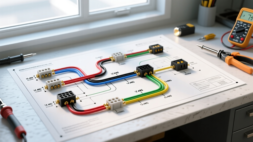
Adhering to proper wire gauge is non-negotiable. Treating a tractor harness like a low-draw household appliance circuit is a leading cause of electrical fires. Below is the definitive wire gauge and color code matrix for a standard 12V Ford 3000 restoration, factoring in voltage drop over the typical 8-foot harness run.
| Circuit Function | Wire Gauge (AWG) | Standard Ford Color | Max Ampacity / Notes |
|---|---|---|---|
| Battery to Starter Solenoid | 1/0 AWG | Black (or Red) | 150A+ / Use fine-strand welding cable |
| Battery to Ammeter | 10 AWG | Yellow | 30A / Must handle full alternator output |
| Ammeter to Ignition Switch | 12 AWG | Yellow | 20A / Main switched power feed |
| Ignition to Coil (Ballast) | 14 AWG | Red w/ White Tracer | 10A / Resistance wire drops voltage to 7-9V |
| Lighting Circuit (Front/Rear) | 14 AWG | Yellow w/ Black Tracer | 15A / Fused via inline 15A AGC fuse |
| Instrument Panel / Gauges | 16 AWG | Green | 5A / Low draw, sensitive to voltage drop |
Step-by-Step Harness Replacement Guide
If your existing wiring is brittle, cracked, or shows signs of copper oxidation (green crust at the terminals), a complete replacement is required. In 2026, a high-quality, OEM-spec replacement harness from specialized suppliers costs between $145 and $195. Follow this procedure for a factory-grade installation:
- Document and Disconnect: Before cutting any zip-ties, photograph every connection. Disconnect the negative battery terminal first to prevent accidental shorts across the un-fused starter solenoid.
- Extract the Old Loom: The main harness on the Ford 3000 routes through a specific channel along the left side of the steering column and down the frame rail. Note how the factory loom passes through the firewall bulkhead using a rubber grommet. Never route bare wires through sheet metal; vibration will strip the insulation in weeks.
- Route the New Harness: Lay the new harness loosely over the chassis. Ensure a minimum clearance of 4 inches from the exhaust manifold and turbocharger (if equipped with an aftermarket setup). Use UV-resistant split-loom tubing over any section exposed to direct sunlight or moving linkage.
- Terminate with Adhesive Heat Shrink: Abandon standard vinyl crimp connectors. Use 3:1 ratio, dual-wall adhesive-lined heat shrink terminals. When heated, the inner wall melts and seals out moisture, preventing the capillary action that draws water into the copper strands. Use a 12-10 AWG yellow terminal for the ammeter and a 16-14 AWG blue terminal for the gauge senders.
- Apply Dielectric Grease: Pack all bulb sockets, the ignition switch rear cavity, and the temperature sender unit with a high-quality silicone dielectric grease to prevent galvanic corrosion.
Troubleshooting Common Ford 3000 Wiring Failures
Even with a perfect wiring diagram, aging components can mimic harness failures. Use a digital multimeter (DMM) to diagnose these specific edge cases:
- The 'No-Spark' Ignition Failure: The Ford 3000 utilizes a resistance wire in the harness to drop the 12V battery voltage down to roughly 7V–9V for the ignition coil. If a previous owner replaced this with standard copper wire, the coil receives a full 12V+ during running, which will burn out the ignition points in less than 10 hours of operation. Measure the voltage at the coil positive terminal with the engine running; if it reads over 10V, you must install an external ceramic ballast resistor.
- Dim Headlights and Slow Cranking: The Ford 3000 relies heavily on chassis grounding. Rust between the cab mounts, the engine block, and the battery box creates massive resistance. Perform a voltage drop test across the ground circuit. Place your DMM's black lead on the battery negative post and the red lead on the headlight housing. With the lights on, any reading above 0.2V indicates a bad ground. The fix is running a dedicated 14 AWG ground wire from the headlight housing directly to the engine block.
- Ammeter Pegging or Melting: The ammeter must be wired in series with the entire electrical load, not in parallel. A common fatal error is wiring the alternator output directly to the battery while leaving the ammeter connected to the starter solenoid. This bypasses the ammeter, rendering it useless, or worse, forces it to carry starter current, melting the dashboard. Reference the NFPA 70 (NEC) guidelines on series metering to ensure your high-amperage charging circuits are routed correctly through the shunt or gauge.
Sourcing OEM-Spec Components in 2026
While universal tractor supply stores sell generic wiring kits, serious restorers turn to dedicated antique tractor networks. Communities like Yesterday's Tractors maintain extensive archives of factory Ford service manuals and offer peer-reviewed advice on harness routing idiosyncrasies specific to the 3000, 3600, and 4000 series. When purchasing a harness, verify that the vendor uses cross-linked polyethylene (XLPE) insulation rather than cheap PVC, as XLPE offers vastly superior abrasion and heat resistance in the harsh environment of a diesel engine bay.
Frequently Asked Questions
Can I use automotive wire from a local auto parts store for my Ford 3000?
You can, but it is not recommended for the engine bay. Standard automotive primary wire (GXL/TXL) is acceptable, but avoid generic hardware store THHN or stranded lamp cord, which lacks the oil, grease, and high-heat resistance required for agricultural machinery.
Does the Ford 3000 wiring diagram include a fuse block?
Original 1965–1975 diagrams rarely feature a centralized multi-fuse block. Instead, they rely on inline glass AGC fuses (typically 15A for lighting, 20A for accessories) and the main ammeter acting as a crude current limiter. Modern restorations highly recommend splicing in a sealed, 6-circuit blade fuse block near the battery for added safety.
Why does my tractor start when I turn the key, but dies when I release it?
This is a classic ignition switch wiring error. The starter solenoid 'I' terminal sends 12V directly to the coil only while cranking (bypassing the ballast resistor). If your ignition switch's 'Run' terminal is not properly feeding the ballast resistance wire, the coil loses power the moment the key returns from 'Start' to 'Run'. Check the ignition switch continuity and verify the resistance wire is intact.