
When a modern refrigerator stops cooling, the immediate instinct for many DIYers is to start swapping parts. However, blindly replacing a $180 Adaptive Defrost Control (ADC) board or a $250 inverter compressor without verifying the circuit is a costly gamble. The secret to accurate, cost-effective appliance repair lies in mastering the refrigerator electrical wiring diagram. By tracing the schematic, you can isolate the exact point of failure, whether it is a $25 start relay, a broken wire in the door hinge harness, or a failed thermistor.
In this guide, we will decode standard and inverter-based refrigerator schematics, providing exact multimeter readings, resistance charts, and step-by-step troubleshooting workflows for the most common cooling failures in 2026.
Decoding the Schematic: Essential Symbols and Line Tracing
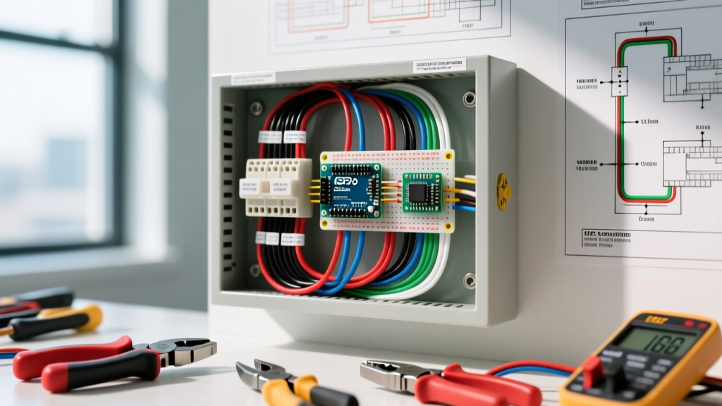
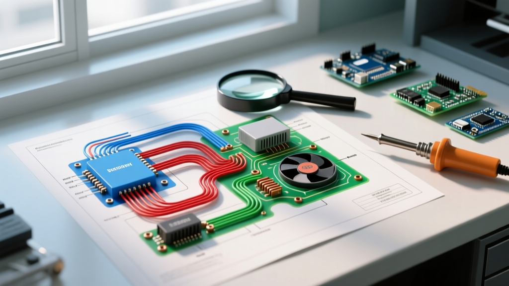
Before touching a multimeter, you must understand the visual language of the wiring diagram. Manufacturers like Whirlpool, GE, and Samsung typically tape the technical schematic inside the lower kickplate grille or the rear access panel.
- Solid Lines: Represent physical wires. A solid black line usually denotes 120VAC Line (L1), while white denotes Neutral (N).
- Dashed Lines: Indicate mechanical linkages or internal switch mechanisms (e.g., the physical push-pin inside a door switch).
- Switch Symbols: Shown as open or closed contacts. A defrost thermostat is typically drawn as 'closed' (the state it is in at room temperature when testing).
- Thermistors: Represented by a resistor symbol with a line striking through it, indicating variable resistance based on temperature.
Pro Tip: Always trace the circuit from the power source (L1) through the switches and loads, and finally back to Neutral (N) or L2. If a component lacks a complete path to Neutral, it will not energize.
Scenario 1: The Compressor Won't Start
The compressor is the heart of the sealed system. When it fails to start, you will typically hear a faint 'click' followed by silence, indicating the thermal overload protector has tripped. How you troubleshoot this depends heavily on whether your unit uses a traditional PTC relay or a modern inverter board.
Testing Standard PTC Start Relays (e.g., Whirlpool WPW10194431)
Standard single-speed compressors rely on a Positive Temperature Coefficient (PTC) start relay and an overload protector. To test the compressor windings using your wiring diagram:
- Unplug the refrigerator and remove the rear lower access panel.
- Detach the PTC relay and overload from the compressor pins.
- Set your multimeter to the Ohms (Ω) setting.
- Measure the resistance between the three terminals: Common (C), Start (S), and Run (R).
Expected Winding Readings:
- Run to Common (R-C): Typically 2.0Ω to 5.0Ω
- Start to Common (S-C): Typically 8.0Ω to 15.0Ω
- Start to Run (S-R): The sum of R-C and S-C (e.g., 10.0Ω to 20.0Ω)
If your multimeter reads 'OL' (Open Line) between any two pins, the internal winding is broken, and the compressor must be replaced. If the windings are intact but the compressor still clicks off, the PTC relay is the culprit. A standard OEM replacement relay costs between $25 and $45.
Diagnosing 2026-Era Inverter Compressors
Modern high-efficiency models (such as the Samsung Bespoke or LG STUDIO series) utilize Digital Inverter compressors. Do not test these for 120VAC. The wiring diagram will show a 3-wire harness connecting the main inverter board directly to the compressor.
The inverter board converts 120VAC into a 3-phase variable-frequency DC voltage. To troubleshoot:
- Check the input voltage to the inverter board: You should read 120VAC between Line and Neutral.
- Check the logic signal: Measure the DC voltage between the logic harness pins (usually 5VDC to 12VDC) sent from the main control board.
- Check the 3-phase output: With the unit calling for cooling, measure the AC voltage (your meter will read the PWM signal as AC) between the three output pins (U-V, V-W, U-W). You should see roughly 60V to 120V AC fluctuating. If input and logic are present but output is zero, the inverter board has failed.
Scenario 2: Defrost System Failures and ADC Boards
If your refrigerator's fresh food section is warm but the freezer is cold (and packed with frost on the back wall), you have a defrost failure. Older units used mechanical defrost timers, but nearly all 2026 models use an Adaptive Defrost Control (ADC) board that relies on thermistor data.
The wiring diagram will show the defrost heater (typically 300W to 600W) wired in series with the defrost thermostat (bimetal switch) and controlled by a relay on the ADC board.
Testing the Defrost Heater and Bimetal Thermostat
Locate the defrost heater wires at the main control board plug. Set your multimeter to Ohms. A functional 400W calrod heater should read between 25Ω and 35Ω. If it reads 'OL', the heater is burned out.
The defrost bimetal thermostat is designed to close at roughly 20°F (-6°C) and open at 55°F (13°C). If you test it at room temperature (70°F+), it should read 'OL'. To properly test it, you must place the sensor in a glass of ice water (32°F) and verify it drops to near 0Ω (continuity).
Defrost Thermistor Resistance Chart
The ADC board determines when to initiate a defrost cycle by reading the resistance of the evaporator thermistor. If the thermistor provides false data, the board will never energize the heater relay. Use this standard 10kΩ reference chart to verify your thermistor against the wiring diagram specifications:
| Temperature (°F / °C) | Expected Resistance (kΩ) | Tolerance Range (+/-) |
|---|---|---|
| 14°F (-10°C) | 16.9 kΩ | 5% |
| 32°F (0°C) | 10.0 kΩ | 5% |
| 50°F (10°C) | 6.3 kΩ | 5% |
| 77°F (25°C) | 3.1 kΩ | 5% |
Note: Always consult your specific model's tech sheet, as GE and Whirlpool use different thermistor curves (e.g., GE often uses a 10kΩ at 77°F standard, while some Whirlpool models use 10kΩ at 32°F).
Scenario 3: Evaporator Fan Motor Diagnostics
A failing evaporator fan will cause uneven cooling and a warm refrigerator compartment. The wiring diagram will specify whether the fan is an AC shaded-pole motor or a DC electronically commutated motor (ECM).
- AC Fan Motors: Test for 120VAC at the harness when the compressor is running and the door switch is depressed. If voltage is present but the fan is dead, replace the motor ($40-$70).
- DC ECM Fan Motors: These are standard in 2026 Energy Star-certified models to reduce power consumption. The wiring diagram will show a 4-wire or 5-wire harness (VCC, GND, PWM Signal, Tachometer Feedback). You cannot simply apply 120VAC to these motors. Test for 12VDC to 14VDC between VCC and GND. If power is present, use the 'Force Defrost/Force Fan' diagnostic mode built into the fridge's control panel to send a PWM signal. If the fan still does not spin, the internal motor driver has failed.
Hidden Failure Points: Wiring Harnesses and Hinges
When the schematic shows a complete circuit, the components test fine, but the load still won't run, suspect a broken wire. The most common failure point in modern French-door refrigerators is the wire harness routed through the bottom door hinge. Every time the door opens and closes, these wires flex. Over 5 to 7 years, the copper strands inside the insulation can snap, creating an invisible open circuit. Use a continuity tester to check the harness from the main board connector to the door switch connector.
Safety Warning: Always disconnect power before performing resistance or continuity tests. According to the National Fire Protection Association (NFPA), electrical malfunctions remain a leading cause of household fires. Furthermore, the Consumer Product Safety Commission (CPSC) warns that appliance capacitors can hold lethal charges even when unplugged. Always discharge run capacitors with a 20,000-ohm, 5-watt resistor before touching compressor terminals.
Conclusion: Let the Diagram Guide Your Multimeter
Troubleshooting a refrigerator without a wiring diagram is like navigating a foreign city without a map. By understanding how to trace L1 to Neutral, identifying the difference between PTC and inverter compressor circuits, and utilizing exact thermistor resistance charts, you can confidently diagnose failures. Whether you are dealing with a simple $30 defrost heater or a complex $250 inverter board, the schematic provides the objective data needed to fix the appliance correctly on the first attempt. For more information on appliance efficiency standards and electrical safety, refer to the EPA ENERGY STAR guidelines and your manufacturer's specific technical service sheets.