
Why Automotive Code Compliance Matters for 12V Audio Systems
When enthusiasts search for a wiring diagram for a Pioneer DEH-150MP, the focus is often purely on functionality—getting the single-DIN CD receiver to power on and play audio. However, from an electrical engineering and safety compliance perspective, a 12-volt DC automotive environment is notoriously hostile. Vibrations, extreme temperature fluctuations, and the presence of combustible materials mean that improper wiring is not just an inconvenience; it is a severe fire hazard.
According to data published by the National Fire Protection Association (NFPA), electrical failures and shorts are among the leading causes of passenger vehicle fires. The Pioneer DEH-150MP is a robust, MOSFET-amplified head unit capable of delivering 50W x 4 channels. While it operates on standard 12V DC, the current draw can exceed 10 amps under peak load. If the wiring harness is not installed to stringent automotive standards, a chafed wire or poor ground can instantly melt insulation and ignite surrounding dashboard plastics.
Safety Directive: Never treat a vehicle's 12V electrical system as a low-risk environment. High amperage at low voltage generates immense heat during a short circuit. All installations must adhere to recognized automotive electrical standards to prevent catastrophic thermal runaway.
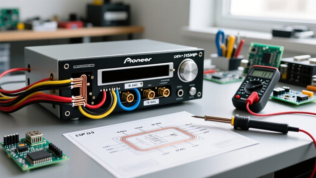
The Pioneer DEH-150MP Wiring Diagram & Color Code Matrix
The DEH-150MP utilizes the standard EIA (Electronic Industries Alliance) color code for aftermarket automotive head units. Below is the comprehensive wiring matrix, augmented with critical safety specifications regarding wire gauge and overcurrent protection.
| Wire Color | Function | Min. Gauge (AWG) | Fuse Requirement | Safety & Routing Notes |
|---|---|---|---|---|
| Yellow | Constant 12V (Memory) | 18 AWG | 10A (ATO/ATC) | Must be fused within 18 inches of the power source. Connects directly to battery or constant fuse tap. |
| Red | Switched 12V (Accessory) | 18 AWG | 10A (ATO/ATC) | Triggers with ignition. Do not splice into airbag, ECU, or CAN-bus ignition circuits. |
| Black | Chassis Ground | 16 AWG | None | Must terminate to bare, unpainted metal using a ring terminal. Never daisy-chain grounds. |
| Blue/White | System Remote Control | 20 AWG | Inline 1A | Turn-on signal for external amplifiers. Max current draw is 200mA; use a relay for high-draw accessories. |
| Orange/White | Illumination | 20 AWG | Vehicle Fuse | Dimmer signal. Shorting this to ground will blow the vehicle's dashboard illumination fuse. |
| White / White-Black | Front Left Speaker (+/-) | 18 AWG | None | Ensure negative (black stripe) is isolated from chassis ground to prevent amplifier short-circuit protection tripping. |
| Grey / Grey-Black | Front Right Speaker (+/-) | 18 AWG | None | Keep speaker wires away from RCA signal cables to prevent high-frequency alternator whine. |
| Green / Green-Black | Rear Left Speaker (+/-) | 18 AWG | None | Route through interior trim, avoiding door hinges where wire fatigue and breaking occur. |
| Purple / Purple-Black | Rear Right Speaker (+/-) | 18 AWG | None | Verify polarity with a 9V battery test or multimeter before finalizing crimps to ensure proper phase alignment. |
SAE Standards for Wire Selection and Routing
A critical failure point in amateur car audio installations is the use of residential wiring. Solid-core copper wire (such as THHN or Romex) is strictly prohibited in mobile applications. Standards outlined by SAE International, specifically SAE J1128 (Low Tension Primary Cable), dictate that automotive wire must be multi-stranded to withstand continuous mechanical vibration and flexing.
Why Stranding and Insulation Matter
Residential wire insulation is designed for static, temperature-controlled environments. In a vehicle dashboard, ambient temperatures can exceed 140°F (60°C) in the summer. SAE J1128 compliant wire utilizes cross-linked polyethylene (XLPE) or high-grade PVC insulation that resists melting, chemical degradation from automotive fluids, and abrasion. When sourcing extension wires for your DEH-150MP harness, always verify that the spool is marked with 'SAE J1128' or 'GXL/TXL' specifications.
Fusing and Overcurrent Protection Protocols
The most common safety violation when installing a Pioneer head unit is improper fuse placement. The DEH-150MP features an internal fuse on the rear chassis, but this is designed to protect the unit's internal PCB, not the vehicle's wiring harness.
- The 18-Inch Rule: The main power feed (Yellow wire) must have an inline ATO/ATC blade fuse holder installed within 18 inches of the power source (whether that is the battery or a high-amperage distribution block). If a short occurs between the power source and the head unit, this fuse prevents the wire from glowing red-hot and igniting the dashboard.
- Fuse Sizing: The DEH-150MP has a maximum current consumption of roughly 10A. Therefore, a 10A or 15A fuse is optimal. Never upsize a fuse to 'fix' a blowing fuse issue; this masks a dead short and invites a fire.
- Fuse Tap Safety: If using a fuse tap (Add-A-Circuit) in the vehicle's interior fuse box, ensure the tap is inserted into a circuit that can handle the additional 10A load without exceeding the ribbon cable's capacity. Avoid tapping into safety-critical circuits like ABS, SRS (Airbags), or ECU power feeds.
Termination Methods: Crimping vs. Soldering
There is a persistent myth in the DIY electronics community that soldering is always superior to crimping. In a high-vibration automotive environment, this is demonstrably false. When solder wicks into multi-stranded wire, it creates a rigid, brittle point exactly where the flexible wire meets the solid solder joint. Over months of driving, engine vibration, and door slamming, this stress concentration causes the copper strands to snap, leading to intermittent connections or arcing.
Best Practice: Use a ratcheting crimp tool to create gas-tight, cold-weld crimps using nylon-insulated or heat-shrink butt connectors. The ratcheting mechanism ensures the exact amount of pressure is applied, deforming the metal barrel tightly around the copper strands without cutting them. Follow this with a heat gun to seal the adhesive-lined heat shrink, preventing moisture ingress and copper oxidation.
Step-by-Step Safe Installation Sequence
Follow this exact sequence to ensure a compliant, hazard-free installation of the Pioneer DEH-150MP:
- Disconnect the Battery: Always remove the negative (-) battery terminal first. Wait 10 minutes before working near the dashboard to allow the SRS (airbag) backup capacitors to discharge.
- Verify Circuits with a Digital Multimeter (DMM): Do not use a cheap incandescent test light. Test lights draw current and can accidentally trigger sensitive CAN-bus modules or deploy airbag squibs. Use a high-impedance DMM to identify constant 12V, switched 12V, and ground at the vehicle's OEM harness.
- Prepare the Harness: Cut and strip the wires on both the Pioneer harness and the vehicle-specific adapter harness. Leave enough slack (at least 6 inches) behind the DIN sleeve for future removal and servicing.
- Execute Crimp Connections: Match colors according to the matrix above. Crimp, heat-shrink, and gently tug each connection to verify mechanical integrity.
- Secure the Ground: Locate a factory grounding bolt behind the dash. Remove the bolt, scrape away any paint or corrosion to expose bare steel, attach the Black wire's ring terminal, and re-tighten to factory torque specifications.
- Loom and Tape: Wrap the entire bundled harness in Tesa cloth automotive wiring tape. This prevents the plastic wire insulation from rattling against the metal dashboard sub-frame and provides an extra layer of abrasion resistance.
- Reconnect and Test: Reattach the negative battery terminal. Turn the ignition to the 'ACC' position and verify power, memory retention, and all four speaker channels before sliding the unit into the DIN cage.
Common Edge Cases and Failure Modes
The 'Memory Drain' Swap
If the DEH-150MP loses its radio presets and clock every time you turn off the car, the Red (Accessory) and Yellow (Constant) wires have been swapped. While this seems like a minor annoyance, connecting the Constant 12V wire to a switched ignition circuit, and the Accessory wire to a constant battery feed, can cause the unit's internal microcontroller to remain in a 'standby' state rather than fully sleeping, leading to a parasitic battery drain over a weekend.
Illumination Wire Shorts
The Orange/White illumination wire is often left unconnected if the vehicle lacks a compatible dimmer circuit. If this bare wire is simply tucked behind the radio without being capped, it can brush against the metal DIN cage. Because this wire is tied to the vehicle's headlight dimmer circuit, a short to ground will instantly blow the vehicle's interior lighting fuse, killing your dashboard backlighting and tail lights.
Alternator Whine and Ground Loops
If you hear a high-pitched whine that increases in pitch with engine RPM, you have a ground loop. This occurs when the head unit and an external amplifier are grounded at different points with different electrical potentials. To resolve this, ensure the DEH-150MP ground and any auxiliary amplifier grounds are tied to the exact same chassis grounding point, creating a single, unified star-ground topology.
For further technical specifications and firmware updates, always refer to the official Pioneer Electronics support documentation. By adhering to these rigorous safety and code compliance standards, your DEH-150MP installation will not only sound exceptional but will remain electrically safe for the lifespan of the vehicle.