
Strategic Planning for Kohler Backup Power Systems
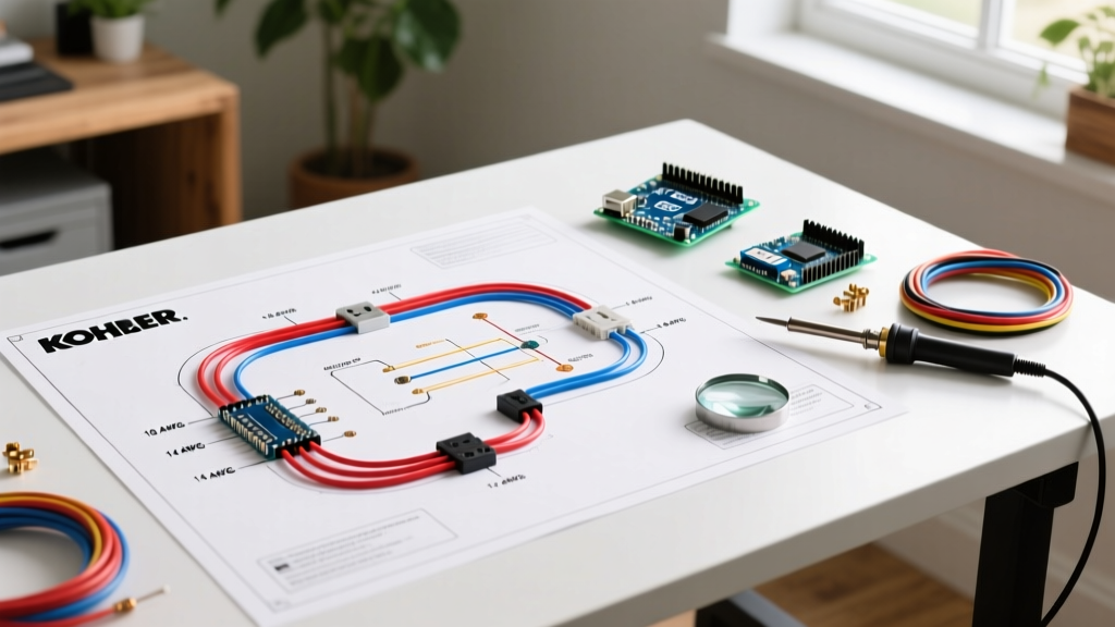
Installing a standby generator is not merely a matter of pulling wire and tightening lugs; it requires a meticulous interpretation of the manufacturer's schematics and a deep understanding of the National Electrical Code (NEC). When planning your installation, the wiring diagram for Kohler generator models—such as the 20RESCL, 26RCL, or the larger 38RCL and 48RCL liquid-cooled units—serves as your primary blueprint. Misinterpreting these diagrams can lead to catastrophic failure modes, including Automatic Transfer Switch (ATS) miscommunication, neutral bonding violations, or severe voltage drop under load.
This installation planning guide dissects the critical elements of Kohler generator wiring diagrams, translating schematic symbols into actionable field procedures, precise wire sizing matrices, and 2026-compliant NEC integration strategies.
Decoding the Kohler Schematic: Controller and Terminal Blocks
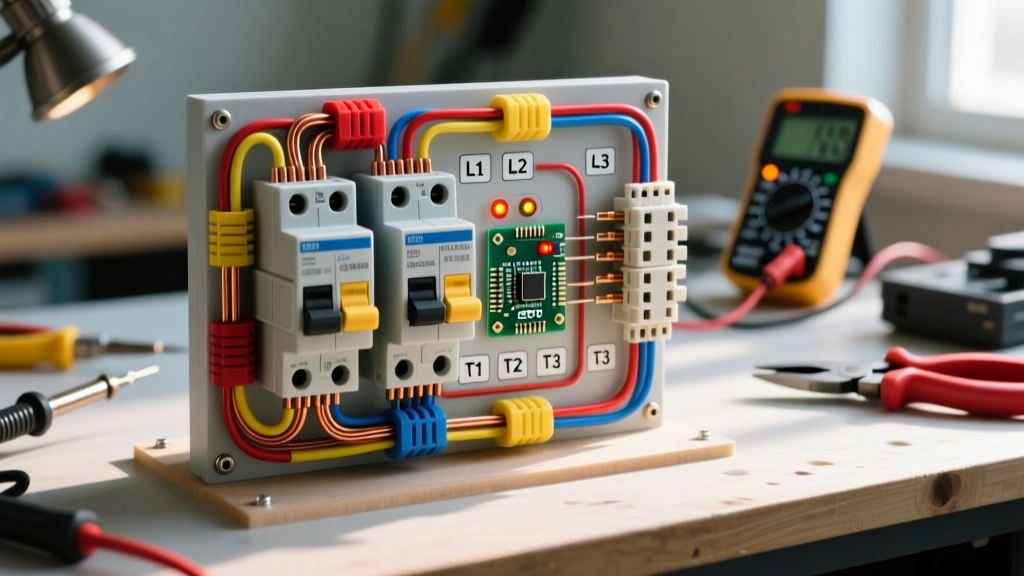
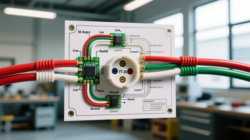
Modern Kohler generators utilize advanced solid-state controllers, primarily the DEC4000 or the RDC2 (Residential Digital Control). The wiring diagram for these controllers centers around the main terminal block, typically labeled TB1 or TB2 on the schematic.
- Utility Sense (L1/L2): The diagram will show a 120V/240V utility sense input. This circuit monitors the grid. If voltage drops below 85% of nominal for a programmable delay (usually 1-3 seconds), the controller initiates the start sequence.
- Remote Start Contacts (Pins 3 & 4): For integrations with third-party smart home panels or solar microgrid controllers, the diagram highlights a dry-contact relay closure circuit. Closing this 12V DC loop signals the generator to start.
- Battery Charger AC Input: Often overlooked by novices, the schematic routes a dedicated 120V AC circuit from the ATS load side or a dedicated breaker back to the generator's internal battery charger. Failing to wire this results in a dead starting battery within 30 days.
Pro-Tip: Never run the utility sense wires in the same conduit as the high-voltage load conductors. As emphasized by industry experts at EC&M (Electrical Construction & Maintenance), inductive coupling from heavy AC loads can induce phantom voltages in the sense wires, causing the DEC4000 controller to falsely read that utility power has been restored, prematurely dropping the load.
Pre-Installation Load Calculation & Wire Sizing Matrix
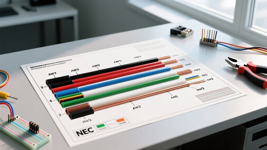
Before purchasing materials, you must cross-reference the generator's output amperity with NEC Article 310 and Chapter 9, Table 8 for voltage drop calculations. The wiring diagram dictates the maximum overcurrent protection, but the physical distance from the generator pad to the ATS dictates the actual wire gauge required to maintain a strict 3% maximum voltage drop.
| Kohler Model | Max Output (kW/kVA) | Rated Amps @ 240V | Min NEC Wire Size (75°C) | Recommended Size (up to 100ft) | Equipment Grounding Conductor |
|---|---|---|---|---|---|
| 20RESCL | 20 kW / 25 kVA | 83.3 A | #3 AWG Copper | #2 AWG THHN | #6 AWG Copper |
| 26RCL | 26 kW / 32.5 kVA | 108.3 A | #1 AWG Copper | 1/0 AWG THHN | #4 AWG Copper |
| 38RCL | 38 kW / 47.5 kVA | 158.3 A | 2/0 AWG Copper | 3/0 AWG THHN | #2 AWG Copper |
| 48RCL | 48 kW / 60 kVA | 200.0 A | 3/0 AWG Copper | 4/0 AWG THHN | 1/0 AWG Copper |
Automatic Transfer Switch (ATS) Integration
The heart of the installation is the ATS. Kohler's residential lineup typically utilizes the RDT (Residential Demand Transfer) or the heavy-duty RSB series. The wiring diagram for the ATS will show three distinct harnesses: Utility Power, Generator Power, and the Control/Communication Cable.
Step-by-Step ATS Control Wiring
- Power Conductor Routing: Pull the utility and generator load conductors through separate knockout hubs if possible, or use a physical divider inside the ATS enclosure to prevent cross-phasing and maintain NEC 300.3 compliance (keeping neutrals and grounds isolated correctly).
- The Control Harness: Kohler RDT switches use a specialized communication cable (often a 4-pin or 6-pin connector). If extending this cable beyond the factory 15-foot length, you must use 18 AWG or 16 AWG shielded stranded wire (such as Belden 8760). The drain wire on the shield must be grounded at the generator end only to prevent ground loops.
- Load Shedding Integration: For 200A whole-home setups, the wiring diagram includes terminals for load-shedding relays. Wire these to your HVAC contactors or EV charger breakers to prevent the generator from stalling during the initial inrush current of heavy inductive loads.
Grounding, Bonding, and NEC Compliance
One of the most critical aspects of the Kohler wiring diagram is the neutral-to-ground bonding configuration. According to the NFPA 70 National Electrical Code (NEC), specifically Article 702 (Optional Standby Systems) and Article 250 (Grounding and Bonding), your wiring topology depends entirely on the ATS type.
- Service-Rated ATS (Separately Derived System): If your Kohler ATS includes a service disconnect and is installed between the utility meter and the main panel, the generator is considered a separately derived source. The wiring diagram will instruct you to bond the neutral to the ground inside the generator and install a dedicated Grounding Electrode System (GES) at the generator pad (typically two 5/8-inch copper-clad ground rods spaced 6 feet apart, tied with #4 bare copper).
- Non-Service-Rated ATS (Non-Separately Derived): If the ATS is installed downstream of the main utility service panel, the neutral must not be bonded at the generator. The wiring diagram will show a floating neutral configuration, relying on the main panel's existing neutral-ground bond and equipment grounding conductors.
As outlined in Kohler Power Systems' official residential documentation, factory-shipped 20RESCL models often come with a removable neutral bonding strap. Verify the position of this strap against your specific ATS wiring diagram before energizing the system. An improper bond will cause nuisance tripping of GFCI/AFCI breakers and create parallel neutral paths, presenting a severe shock hazard.
2026 Material Costs and Planning Budget
When planning your installation, accurate budgeting is essential. Copper prices and solid-state component costs have shifted in 2026. Below is a realistic material cost breakdown for a standard 20kW Kohler installation with a 60-foot wire run:
- 2/0 AWG THHN Copper (4 conductors): ~$14.50 per foot × 240 ft total = $3,480
- #4 AWG Bare Copper Ground: ~$6.20 per foot × 60 ft = $372
- 18 AWG Shielded Control Wire: ~$1.10 per foot × 100 ft = $110
- 2-inch PVC Schedule 80 Conduit & Fittings: ~$450
- Kohler RDT-Pro-JFSP-0200 (200A Service-Rated ATS): ~$1,850
- Miscellaneous Lugs, Anti-Oxide Paste, and Hardware: ~$150
Total estimated material cost (excluding the generator unit and labor): $6,412
Troubleshooting Edge Cases and Common Pitfalls
Even with a perfect wiring diagram, field conditions introduce variables. Keep these troubleshooting frameworks in mind during the commissioning phase:
1. The 'Cranking but Not Starting' Phantom
If the generator cranks continuously but fails to fire, check the wiring diagram for the ignition enable relay or the fuel solenoid circuit. A voltage drop of more than 1.5V on the DC control wiring between the battery and the controller will prevent the DEC4000 from opening the fuel valve, even if the starter motor engages.
2. ATS Failure to Transfer Back to Utility
If the generator runs but refuses to transfer back to the grid once utility power is restored, the issue is almost always in the utility sense wiring. Use a true-RMS multimeter to verify that exactly 240V (±5%) is present at the TB1 utility sense terminals. If you read 120V on one leg and 0V on the other, a utility fuse has blown, or a neutral wire has backed out of a lug upstream.
3. Exercise Timer Desynchronization
Kohler generators perform a weekly 20-minute exercise cycle. If the unit exercises at random times, verify the AC battery charger wiring. The controller relies on the zero-crossing of the AC sine wave from the charger circuit to maintain its internal real-time clock. If wired to a DC source or a modified sine wave inverter, the clock will drift, causing erratic exercise schedules.
Final Commissioning Checklist
Before closing the ATS and generator enclosures, perform a final verification against the schematic:
- [ ] Torque all power lugs to the exact inch-pound specifications listed on the generator's data tag (typically 250-350 in-lbs for 2/0 AWG).
- [ ] Verify the neutral bonding strap matches the ATS topology (Service-rated vs. Non-service-rated).
- [ ] Confirm the grounding electrode conductor is irreversibly spliced or run continuously to the ground rods without any intermediate disconnects.
- [ ] Test the manual override switch on the ATS to ensure mechanical transfer operates smoothly without binding.
By treating the wiring diagram not just as a map, but as a strict engineering document, you ensure your Kohler generator will deliver reliable, code-compliant backup power for decades.