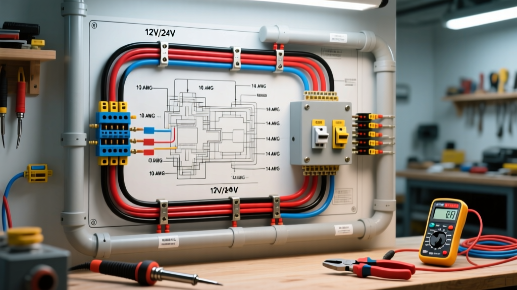

Decoding the Electrical Wiring Diagram for Boats
Reading and executing an electrical wiring diagram for boats requires a fundamentally different approach than automotive or residential wiring. The marine environment is uniquely hostile to electrical systems, combining constant vibration, high humidity, and corrosive salt air. A wiring diagram that works perfectly in a car will often lead to catastrophic failure, voltage drop, or even a marine fire when translated to a vessel.
As of 2026, the gold standard for marine electrical design remains the ABYC (American Boat & Yacht Council) E-11 Standard for AC and DC electrical systems. This guide breaks down the critical elements of marine wiring diagrams, focusing on ABYC color codes, precise wire gauge calculations, and the specific materials required to ensure your vessel's electrical backbone survives the elements.
CRITICAL MARINE WARNING: Never use standard automotive wire (SAE J1128 Type GXL/TXL) on a boat. Automotive wire features untinned copper and fewer, thicker strands. Marine environments demand Type III stranding (UL 1426 / SAE J378), which utilizes tinned copper wire with a higher strand count to resist corrosion and vibration fatigue.
ABYC E-11 Color Code Matrix for DC Systems
Unlike household wiring, where white is neutral and black is hot, marine DC systems follow a strict color-coding convention to prevent lethal cross-connections between AC shore power and DC battery banks. When reviewing your electrical wiring diagram for boats, ensure the schematic adheres to these ABYC color codes.
| Wire Color | Abbreviation | Application / Purpose |
|---|---|---|
| Red | RD | DC Positive (Ungrounded) |
| Black or Yellow | BK / Y | DC Negative (Grounded) (Yellow is preferred to avoid AC confusion) |
| Dark Blue | DB | Fuses, Breakers, and Lighting Switches |
| Light Blue | LB | Oil Pressure Alarm / Navigation Lights |
| Brown | BR | Pumps, Alternator Armature, Generator Start |
| Orange | O | Distribution Panels, Ignition, Instruments |
| Yellow with Red Stripe | Y/R | Engine Harness (Sender to Gauge) |
| White | W | Speedometer / Tachometer Signal |
Wire Gauge Selection & The Voltage Drop Rule
The most common mistake DIY boaters make when following an electrical wiring diagram for boats is sizing wire based solely on ampacity (the maximum current a wire can carry before melting). In marine 12V and 24V systems, voltage drop is the true limiting factor. Because marine systems operate at low voltage, even a small resistance over a long wire run will result in a massive percentage of voltage loss, starving sensitive electronics and causing motors to overheat.
The 3% vs. 10% Voltage Drop Thresholds
- 3% Maximum Drop: Required for critical electronics, navigation lights, VHF radios, chartplotters, and windlasses. A VHF radio dropping from 12.6V to 11.8V can severely reduce transmission range and cause the unit to reboot during high-draw transmission.
- 10% Maximum Drop: Acceptable for general non-critical loads like cabin lighting, wipers, and bait pumps.
According to West Marine's Wire Size Advisor, calculating the correct AWG requires knowing the total round-trip circuit length (positive + negative wire), the maximum amperage draw, and the system voltage.
Marine Wire Gauge Sizing Chart (12V DC System, 3% Drop)
| Appliance / Load | Avg. Amps | Run Length (One Way) | Required AWG (Tinned) |
|---|---|---|---|
| VHF Radio (Transmitting) | 6A | 15 ft | 12 AWG |
| Chartplotter / MFD | 3A | 12 ft | 14 AWG |
| Electric Windlass | 120A | 25 ft | 1/0 AWG (0 AWG) |
| Bilge Pump (Auto) | 4A | 20 ft | 12 AWG |
| Macerator Pump | 15A | 18 ft | 8 AWG |
Advanced Diagram Edge Cases: NMEA 2000 Networks
Modern electrical wiring diagrams for boats almost always include an NMEA 2000 (N2K) backbone. N2K uses a standardized DeviceNet Micro-C 5-pin connector. When wiring the backbone power tee, you must adhere to the specific pinout and wire gauge requirements:
- Pin 1 (Shield):strong> Drain wire (bare).
- Pin 2 (V+):strong> Red wire (12V Power) - Must be 12 AWG for the main backbone power insert.
- Pin 3 (CAN-L):strong> Blue wire (Data Low) - 22 AWG signal pair.
- Pin 4 (CAN-H):strong> White wire (Data High) - 22 AWG signal pair.
- Pin 5 (V-):strong> Black wire (Ground) - Must be 12 AWG.
Pro Tip: Never splice N2K signal wires using standard butt connectors. The high-frequency CAN bus signals are highly susceptible to impedance mismatches and corrosion. Always use certified T-connectors or network terminators.
Execution: Crimping and Heat Shrink Standards
A flawless wiring diagram is useless if the physical terminations fail. In 2026, the accepted marine standard for terminating wire is the hex-crimp with adhesive-lined heat shrink method. Soldering is explicitly discouraged by the ABYC for primary wire terminations because solder wicks up into the wire strands via capillary action, creating a rigid, brittle point that will snap under engine vibration.
Essential Marine Wiring Tools
- Wire: Ancor Marine Grade Tinned Copper (Approx. $1.30/ft for 8 AWG; $4.80/ft for 1/0 AWG battery cable).
- Crimper: FTZ Industries Hex Crimp Tool (Approx. $125). This tool applies a uniform 360-degree hexagonal crush, ensuring a gas-tight connection that prevents oxygen and moisture from reaching the copper strands.
- Heat Shrink: 3M EPS300 Adhesive-Lined Heat Shrink (3:1 shrink ratio). When heated, the inner thermoplastic adhesive melts and flows around the wire insulation, creating a waterproof seal that blocks salt spray and prevents wicking.
Common Marine Wiring Failure Modes
When troubleshooting or designing an electrical wiring diagram for boats, anticipate these specific failure modes:
- Galvanic Corrosion at Terminals: Occurs when dissimilar metals (e.g., aluminum bus bars and copper lugs) are mated without dielectric grease or proper plating. Always use tin-plated copper bus bars and apply a marine-grade anti-corrosion compound like NO-OX-ID.
- UV Degradation of Insulation: Standard PVC wire insulation becomes brittle and cracks when exposed to direct sunlight or high-heat engine bay environments. Ensure your wire jacket is rated for marine UV exposure or route all wiring through corrugated split loom tubing.
- Vibration Fatigue at Lugs: Using ring terminals that are too large for the stud size allows the terminal to pivot, eventually fatiguing and breaking the copper strands inside the heat shrink. Always match the terminal hole size exactly to the stud diameter (e.g., 5/16' lug for a 5/16' stud).
- Undersized Fusing: Fuses protect the wire, not the appliance. If your diagram calls for 10 AWG wire (rated for 30A) but the appliance draws 5A, you should fuse the circuit at 30A to protect the wire from short-circuit fires, while relying on the appliance's internal breaker for component protection.
Summary
Creating and executing an electrical wiring diagram for boats requires strict adherence to ABYC color codes, meticulous voltage drop calculations, and the use of tinned, Type III marine wire. By prioritizing 3% voltage drop limits for critical electronics and utilizing hex-crimp terminations with adhesive heat shrink, you ensure your vessel's electrical system remains safe, reliable, and compliant with modern marine surveying standards.