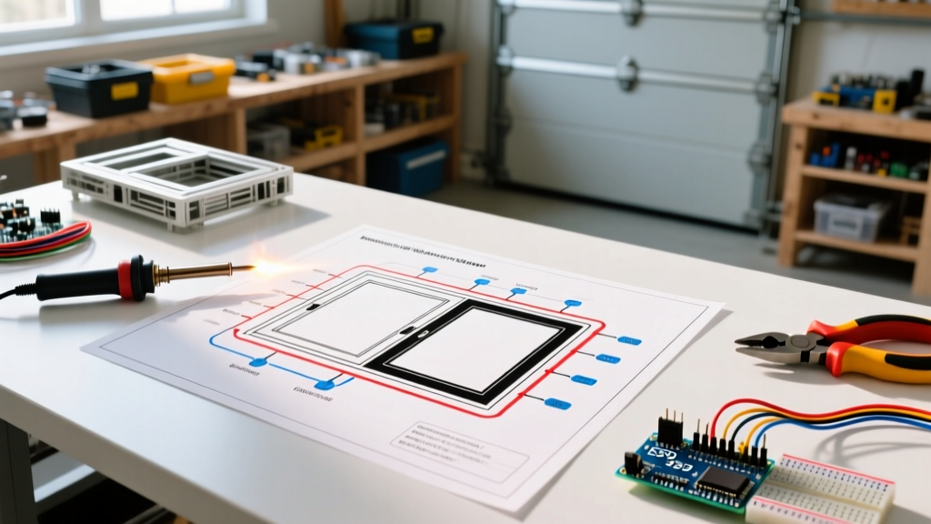

The Anatomy of a Universal Power Window Circuit
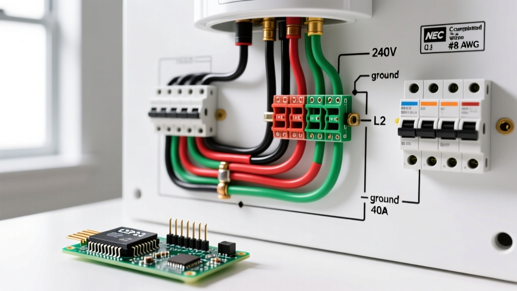
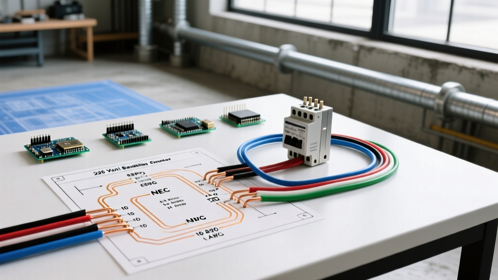
Upgrading a classic car, street rod, or custom off-road rig with electric glass requires more than just bolting motors to the door channels. The foundation of a reliable system lies in a properly executed wiring diagram for power windows. Unlike simple lighting circuits, power window motors require polarity reversal to change direction, meaning the electrical architecture must handle high inrush currents, bidirectional switching, and strict voltage-drop tolerances. In 2026, with the proliferation of high-torque brushless window motors and advanced smart-relays, understanding the core electrical principles is critical to preventing melted switches, blown fuses, and sluggish window operation.
⚠️ CRITICAL SAFETY DIRECTIVE: Never wire power window motors directly through the dashboard switches without high-amperage relays. Direct switching forces 20+ amps of continuous current through small switch contacts, leading to rapid thermal degradation, voltage drop, and potential electrical fires. Always use a relay-switched topology.
Step 1: Load Calculation and Wire Gauge Selection
Before cutting a single wire, you must calculate the maximum current draw of your specific window motors. Standard 12V brushed DC window motors typically draw between 6 to 12 amps during normal operation, but their stall current (the amperage drawn when the window hits the top or bottom bump stops and the motor briefly stalls before the breaker trips) can surge to 25–40 amps. Wire gauge must be selected based on this peak stall current and the total length of the wire run to prevent voltage drop.
According to the SAE J1128 standard for low-tension automotive primary cable, wire sizing must account for the high-temperature environment inside vehicle doors and kick panels. Below is the definitive wire gauge matrix for a standard 2-door or 4-door power window installation.
| Circuit Segment | Recommended AWG (SAE) | Max Continuous Amps | Max Run Length (One Way) |
|---|---|---|---|
| Main Battery Feed to Breaker | 10 AWG | 40A | 15 feet |
| Breaker to Relay Power (Pin 30) | 12 AWG | 30A | 10 feet |
| Relay Output to DPDT Switch | 14 AWG | 20A | 12 feet |
| Switch to Window Motor Legs | 14 AWG | 20A | 8 feet (inside door) |
| Switch Illumination / Dash Acc | 18 AWG | 3A | 20 feet |
Step 2: Selecting the Right Overcurrent Protection
A common mistake in amateur custom builds is using standard ATC/ATO blade fuses for power window main feeds. When a window reaches the top of its travel, the motor stalls for a fraction of a second, spiking the amperage. A standard 20A blade fuse will suffer from 'nuisance blowing' due to these micro-stall events. Furthermore, if a window track binds, you want the circuit to cut power, cool down, and reset, rather than leaving you with a dead window and a blown fuse you cannot easily locate.
PTC Auto-Reset Circuit Breakers vs. Standard Fuses
- Type 1 Auto-Reset (Thermal): Uses a bimetallic strip. Cycles on and off continuously during a fault. Not recommended for modern sensitive ECUs, but acceptable for isolated window circuits.
- PTC (Polymeric Positive Temperature Coefficient) Solid-State Breakers: The 2026 industry standard. As current exceeds the threshold, the polymer heats up and exponentially increases resistance, effectively choking the current to a near-zero trickle. It remains in a safe 'tripped' state until the fault is cleared and the ignition is cycled. Refer to Littelfuse automotive circuit protection guidelines for selecting the correct 30A or 40A PTC breaker for high-inrush motor loads.
Step 3: Decoding the Wiring Diagram for Power Windows
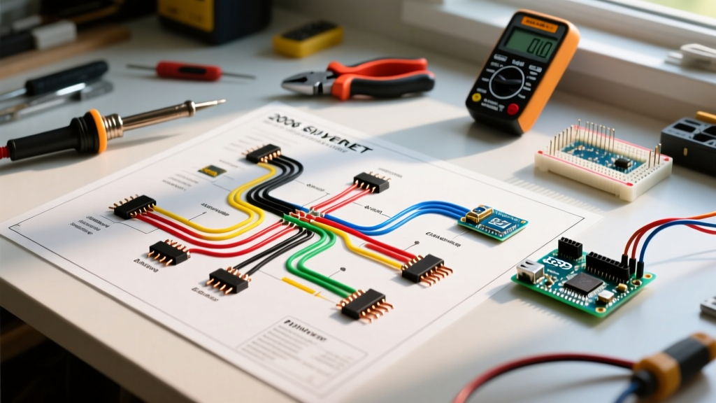
The core of any universal wiring diagram for power windows relies on a DPDT (Double Pole, Double Throw) switch configuration paired with two or more 5-pin automotive relays. The switch does not supply power to the motor; it merely acts as a logic gate that triggers the relays to route high-amperage 12V power and ground to the correct motor terminals.
The 5-Pin ISO 7588 Relay Logic
For a standard two-window setup, you will use four 40A Bosch-style 5-pin relays (two per window). Understanding the pinout is non-negotiable for a clean installation:
- Pin 30 (Common): High-amp 12V input from the PTC circuit breaker.
- Pin 87 (Normally Open): High-amp 12V output to the window switch/motor. (Used for window actuation).
- Pin 87a (Normally Closed): Connected to ground. This provides a dynamic brake path for the motor when the relay is at rest, stopping the window instantly when you release the switch.
- Pin 85 (Coil Ground): Connected to a clean chassis ground.
- Pin 86 (Coil Power): Low-amp 12V trigger input from the DPDT dashboard switch.
The Polarity Reversal Matrix
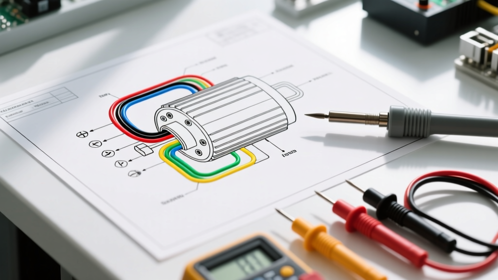
Window motors have two terminals (usually labeled A and B, or Green and Blue). To roll the window up, Terminal A receives +12V and Terminal B receives Ground. To roll down, Terminal B receives +12V and Terminal A receives Ground. The DPDT switch contains internal jumper bridges that cross-connect the relay trigger pins, ensuring that pressing 'Up' energizes the 'Up' relay while simultaneously grounding the 'Down' motor leg through the resting 87a pin of the opposing relay.
Step 4: Routing, Grounding, and Edge-Case Troubleshooting
Even with a perfect schematic, physical installation errors cause 90% of power window failures. Adhering to general NFPA 70 electrical safety principles regarding overcurrent and grounding ensures longevity and fire prevention in mobile applications.
Common Failure Modes and Solutions
| Symptom | Root Cause Analysis | Diagnostic & Repair Action |
|---|---|---|
| Window moves slowly, motor gets hot | Severe voltage drop due to undersized wire or poor ground. | Perform a voltage drop test across the ground wire. If >0.2V under load, scrape paint to bare metal and use a star washer for the ground ring terminal. |
| Window reverses direction before hitting top | Binding tracks causing premature stall-current spike, tripping PTC breaker. | Lubricate run channels with silicone spray. Check for bent regulator arms. Do not increase breaker amperage to compensate for mechanical binding. |
| Switch feels hot to the touch | Direct switching without relays, or relay coil flyback diodes missing. | Verify relays are in use. Install 1N4001 flyback diodes across relay pins 85 and 86 to prevent inductive voltage spikes from melting switch contacts. |
| Window creeps down over time | Leakage current through worn switch contacts or lack of dynamic braking. | Ensure Pin 87a on the relays is tied to a dedicated, clean ground to engage the motor's internal electromagnetic brake when at rest. |
Step 5: 2026 Market Overview - Recommended Kits and Components
When planning your installation, deciding between a fully integrated kit and sourcing individual OEM components impacts both your budget and installation time. Here is a breakdown of the top-tier options available for custom builds in 2026.
1. AutoLoc APW2 (2-Door Universal Kit)
- Price Range: $160 - $185
- Contents: Two high-torque 12V motors, pre-terminated relay harness, DPDT switches with billet bezels, 30A inline breaker.
- Pros: Harness is fully loomed and color-coded; relay logic is pre-wired, reducing schematic errors.
- Cons: Included wire is exactly 14 AWG; heavy-duty custom builds may require upgrading the main feed to 10 AWG.
2. Spal PW100 (Premium Universal Kit)
- Price Range: $230 - $260
- Contents: Brushless motors (longer lifespan, lower amp draw), solid-state PTC breakers, illuminated switches.
- Pros: Brushless motors draw roughly 30% less amperage, drastically reducing voltage drop concerns on long wire runs.
- Cons: Higher upfront cost; requires specific Spal control modules rather than standard Bosch relays.
3. Sourcing Individual OEM Components (The Purist Route)
- Price Range: $80 - $120 (Total)
- Contents: Junkyard or aftermarket GM-style DPDT switches, four standard 40A ISO relays, bulk SAE J1128 wire, Littelfuse PTC breaker.
- Pros: Ultimate customization of wire routing and lengths; easy to source replacement switches at any local auto parts store globally.
- Cons: Requires advanced crimping skills, custom relay harness fabrication, and deep understanding of the polarity-reversal matrix.
Final Pre-Flight Checklist
Before connecting the main battery feed to your newly installed PTC breaker, verify the following:
- All relay pins 85 are tied to a centralized, painted-free chassis ground bus.
- Switch illumination wires are routed to a dimmer-controlled accessory circuit, not a constant 12V source.
- Wire grommets are installed where the harness passes from the A-pillar into the door shell to prevent insulation shear.
- A multimeter confirms 12.2V or higher at the motor terminals under load while the engine is off.
By treating your wiring diagram for power windows as a high-current logic circuit rather than a simple accessory feed, you guarantee a smooth, reliable, and safe installation that will outlast the vehicle itself.