
Mastering Kubota Tractor Electrical Diagnostics
Modern Kubota tractors, from the compact BX2380 to the heavy-duty M7060, rely on intricate 12V DC electrical networks to manage everything from engine cranking to hydrostatic transmission safety interlocks. When a circuit fails, guessing leads to replaced parts, wasted labor, and potential harness damage. The definitive solution is consulting the factory electrical Kubota wiring diagram PDF found in the official Workshop Manual (WSM). This guide provides a deep-dive, expert-level methodology for reading these schematics, performing voltage drop tests, and isolating faults in starter, PTO, and Operator Presence (OP1) circuits.
Decoding the Electrical Kubota Wiring Diagram PDF
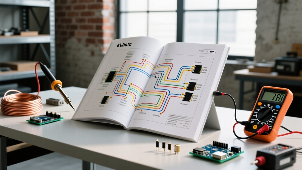
Kubota schematics are not intuitive to novices. Unlike standard automotive diagrams that use physical routing layouts, Kubota PDFs utilize a logical ladder-style schematic mapped to a coordinate grid (e.g., A1-F5). Understanding the nomenclature and color-coding is the first step in effective troubleshooting.
Kubota Wire Color Code Standards
Kubota uses a standardized two-letter color code system. The first letter represents the primary wire color, and the second letter (if present) represents the tracer (stripe) color. For example, WB is White with a Black tracer.
| Color Code | Primary / Tracer | Typical Circuit Application | Standard Wire Gauge (AWG) |
|---|---|---|---|
| R | Red | Main Battery Power (Unswitched) | 10 to 4 AWG |
| B | Black | Chassis Ground / Return Path | 18 to 10 AWG |
| W | White | Switched Power (Key ON / ACC) | 18 to 14 AWG |
| Y | Yellow | Lighting Circuits (Headlamps, Work Lights) | 16 to 14 AWG |
| BR | Black / Red Tracer | Alternator Excitation / Sense Wire | 18 AWG |
| SB | Slate (Gray) / Black | Sensor Signals (Oil Pressure, Coolant Temp) | 20 to 18 AWG |
Essential Diagnostic Tools for Kubota Circuits
Reading the PDF is only half the battle; verifying the physical circuit requires precision tools. Cheap multimeters often lack the input impedance required to diagnose high-resistance faults in modern Kubota solid-state relays.
| Tool | Recommended Model | 2026 Est. Price | Diagnostic Purpose |
|---|---|---|---|
| Digital Multimeter (DMM) | Fluke 87V MAX | $380 - $420 | Voltage drop, resistance, continuity, and diode testing. |
| Circuit Tester / Power Probe | Power Probe PT (IV) | $210 - $250 | Instantly sourcing 12V power or ground to actuate solenoids and relays. |
| Wire Piercing Probes | Lisle 44950 Set | $25 - $35 | Tapping into sealed harnesses without stripping insulation. |
| Thermal Imaging Camera | FLIR ONE Pro | $390 - $450 | Identifying high-resistance connections generating excess heat. |
Step-by-Step Troubleshooting: The Starter Solenoid Circuit
A common issue across the Kubota L-Series (e.g., L3901, L4701) is a "no-crank" condition despite a fully charged 12V battery. The electrical Kubota wiring diagram PDF reveals that the starter solenoid does not receive power directly from the ignition switch. Instead, it passes through the Main Fuse, the Key Switch, the OP1 (Operator Presence) Safety Relay, and finally the Starter Relay.
Executing a Voltage Drop Test
According to Fluke's official testing guidelines, a voltage drop test is superior to a simple continuity test because it evaluates the circuit under a live load. Here is how to trace the Kubota starter circuit using the PDF:
- Verify Source Voltage: Set your DMM to DC Volts. Measure across the battery posts (not the cable clamps). A healthy Kubota AGM or flooded lead-acid battery should read 12.6V to 12.8V static. (See Battery University for detailed state-of-charge metrics).
- Test the Main Fuse Block: Locate the 80A main slow-blow fuse. Place the red probe on the battery positive post and the black probe on the load side of the 80A fuse. Have an assistant turn the key to START. A reading above 0.2V indicates corrosion or a loose terminal at the fuse block.
- Trace the OP1 Relay Logic: Consult the PDF grid (usually Section 9 in the WSM). The OP1 relay requires a ground path through the seat safety switch and the PTO switch (if equipped) to energize. If the key switch outputs 12V to the OP1 relay coil (Pin 86) but the relay doesn't click, check the ground path at Pin 85. A faulty seat switch will show infinite resistance (Open Loop) when depressed.
- Starter Relay Output: Measure voltage at the starter solenoid "S" terminal (usually a spade connector with a Yellow/Red or White/Red wire). During cranking, this must read within 0.5V of battery voltage. If it reads 8V, you have a voltage drop in the harness between the relay and the starter.
Expert Warning: Never bypass the OP1 safety relay by jumping the starter solenoid to diagnose a no-crank issue on a hydrostatic Kubota. If the hydrostatic pedal is not in neutral, the tractor will lurch forward or backward immediately upon cranking, posing a severe crushing hazard.
Diagnosing PTO Clutch and Charging System Faults
The Power Take-Off (PTO) clutch on mid-size Kubota tractors (like the MX5400) is an electromagnetic coil that engages the implement driveline. Failures here are frequently misdiagnosed as a bad clutch when the fault actually lies in the wiring harness.
PTO Clutch Coil Resistance Testing
Using the wiring diagram, locate the PTO clutch connector (typically a 2-pin weather-pack connector near the rear axle). Disconnect the harness and measure the resistance across the clutch coil pins.
- Normal Range: 2.5 to 4.0 Ohms (at 68°F / 20°C).
- Short Circuit: Below 1.0 Ohm (will blow the 15A PTO fuse instantly).
- Open Circuit: Infinite / OL (internal coil wire break, requires $250-$350 clutch replacement).
Alternator and Battery Sense Wire Diagnostics
If your Kubota dashboard shows a battery warning light, or the battery reads below 13.2V while the engine is at 1500 RPM, the alternator is undercharging. The wiring diagram highlights a critical, often overlooked wire: the Sense Wire (usually Black/Red or White). This wire connects directly from the alternator "S" terminal to the positive battery post or main fuse block. If this 18 AWG sense wire is broken or corroded, the alternator's internal regulator cannot "see" the battery voltage and will default to a low-output state to protect itself. Always verify continuity on the sense wire before condemning a $200 OEM alternator.
Navigating and Sourcing OEM Kubota PDF Manuals
To get the exact electrical Kubota wiring diagram PDF for your machine, avoid third-party "tractor manual" aggregator sites that often sell generic, non-model-specific schematics.
- Official Kubota Tech Resources: Use the Kubota USA Official Manual Lookup. You will need your exact model number and serial number to download the correct WSM (Workshop Manual).
- PDF Navigation Tricks: Kubota WSM PDFs are often 400+ pages. Use the PDF bookmark panel to jump directly to the "Electrical System" or "Wiring Diagrams" section. Use the
Ctrl+F(orCmd+F) search function to look for specific component names like "Fuel Stop Solenoid" or "Glow Relay" to find the exact page grid. - Printing for the Shop: Print the specific schematic pages on 11x17 (Tabloid) paper. Standard 8.5x11 letter paper makes reading the 14-pin connector pinouts and grid coordinates nearly impossible in a dimly lit shop environment.
Frequently Asked Questions (FAQ)
Why does my Kubota wiring diagram show a diode in the PTO circuit?
Kubota frequently installs a flyback suppression diode across the PTO relay coil or directly at the clutch connector. When the electromagnetic field of the PTO clutch collapses (when you turn it off), it generates a high-voltage reverse spike that can fry the dashboard PCB or the OP1 safety module. If your PDF shows a diode symbol (a triangle with a line), test it using your DMM's diode setting. It should read 0.4V to 0.6V in one direction and "OL" in the reverse direction.
Can I use automotive primary wire to repair a Kubota harness?
Yes, but you must match the SAE J1128 standard for thin-wall (GXL or TXL) cross-linked polyethylene insulation. Standard PVC automotive wire from big-box stores will melt if routed near the Kubota exhaust manifold or EGR cooler. Always use adhesive-lined marine-grade heat shrink (3M or Ancor) when splicing to prevent moisture ingress, which causes rapid green-crust corrosion in Kubota multi-pin connectors.
How do I identify a parasitic battery draw using the wiring diagram?
If your Kubota battery dies after sitting for 48 hours, disconnect the negative battery cable and place your DMM (set to 10A DC) in series between the negative post and the disconnected cable. With the key OFF and all doors/hoods closed, a normal draw is under 30 milliamps (0.03A). If the draw is higher, consult the wiring diagram to identify circuits that have constant battery power (unswitched Red wires). Pull the corresponding fuses one by one (e.g., Radio, Work Lights, Telematics/GPS module) until the amperage drops to normal, isolating the faulty component.