
Understanding the Wiring Diagram for 3 Wire Alternator Systems
When upgrading a classic vehicle, swapping to an EFI system, or restoring a daily driver, the alternator is the heartbeat of your electrical system. While modern vehicles use complex CAN-bus controlled generators, the classic internally regulated 3-wire alternator—most notably the GM 10SI, 12SI, and modern high-output equivalents like the Powermaster 7100 series—remains the gold standard for DIY automotive wiring. Understanding the wiring diagram for 3 wire alternator topologies is critical to preventing undercharging, overcharging, and catastrophic wiring harness fires.
Unlike simpler 1-wire setups, a true 3-wire configuration utilizes dedicated circuits for battery sensing and field excitation. This ensures the voltage regulator receives accurate data and responds instantly to heavy electrical loads, such as cooling fans, fuel pumps, and high-draw ignition systems. In this comprehensive reference guide, we break down the exact pinouts, SAE-compliant wire gauge requirements, and real-world failure modes you need to know for a flawless installation in 2026 and beyond.
The 3-Wire Pinout Matrix (GM 10SI / 12SI Standard)
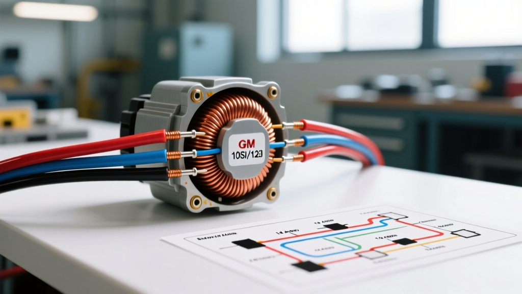
The physical connector on a standard GM-style 3-wire alternator features two spade terminals (labeled 1 and 2) positioned in a specific clocking orientation, alongside a large threaded output stud. Below is the definitive pinout reference matrix.
| Terminal / Stud | Designation | Primary Function | Typical Wire Gauge | Destination |
|---|---|---|---|---|
| Large Stud | BAT (B+ / Output) | Main DC power output to the battery and vehicle bus. | 8 AWG to 4 AWG | Battery Positive or Starter Solenoid |
| Spade #2 | Sense (S) | Reads actual system voltage to regulate alternator output. | 10 AWG to 12 AWG | Battery Positive or Main Distribution Block |
| Spade #1 | Exciter (L / IGN) | Provides initial field current to 'wake up' the regulator. | 16 AWG to 18 AWG | Ignition Switch (via dash indicator bulb) |
Wire Gauge Selection & SAE Standards
Selecting the correct wire gauge is non-negotiable. Automotive under-hood environments routinely exceed 125°C (257°F). According to SAE J1128 standards for high-temperature automotive primary wire, you must size your conductors based on the alternator's maximum rated amperage, not its cruising amperage. Using undersized wire on the BAT terminal causes severe voltage drop, forcing the alternator to work harder, generate excess heat, and ultimately fail.
| Alternator Max Output | Minimum BAT Wire Gauge (Up to 5 ft) | Minimum BAT Wire Gauge (5 to 10 ft) | Required Inline Fuse (125% Rule) |
|---|---|---|---|
| 63A - 80A (GM 10SI) | 8 AWG | 6 AWG | 100A ANL / MEGA |
| 94A - 105A (GM 12SI) | 6 AWG | 4 AWG | 125A ANL / MEGA |
| 110A - 140A (CS130D / Aftermarket) | 4 AWG | 2 AWG | 175A ANL / MEGA |
Step-by-Step Execution & Routing Rules
To properly execute the wiring diagram for 3 wire alternator setups, follow these specific routing and termination procedures.
1. The BAT (Output) Circuit
This is the heavy lifter. Always use a high-strand-count, pure copper SAE wire (avoid Copper Clad Aluminum / CCA). Terminate the alternator end with a tinned, heat-shrink ring terminal. The destination should be the main battery positive post or a high-amperage distribution busbar. Safety Critical: You must install a Littelfuse MEGA or Bussmann ANL fuse within 18 inches of the battery positive connection. If the alternator output wire shorts to the chassis, an unfused circuit will instantly weld the wire to the frame and start a fire.
2. The Sense (#2) Circuit
The sense wire is the most misunderstood part of the 3-wire diagram. Its job is to tell the internal regulator what the voltage is at the battery. If you connect the sense wire directly to the alternator's BAT stud (a common lazy shortcut), the regulator measures voltage at the alternator, ignoring the voltage drop across the wiring harness. This results in the battery receiving only 13.2V while the alternator pushes 14.4V. Route the #2 sense wire directly to the battery positive terminal or the positive side of the main distribution block. Use a 10 AWG wire and fuse it with a 10A inline blade fuse near the battery.
3. The Exciter (#1) Circuit
The exciter wire provides the initial 'bootstrap' current to energize the rotor field. It must be connected to an ignition-switched 12V source. In factory GM wiring diagrams, this wire routes through a dashboard indicator bulb (typically a #194 incandescent). The resistance of the bulb filament provides the necessary current limiting. When the alternator begins spinning and generating power, it sends 12V back up the exciter wire, equalizing the voltage on both sides of the bulb, causing it to turn off.
Expert Warning: LED Dash Bulb Backfeed
If you have upgraded your dashboard to LED bulbs in 2026, the LED will not draw enough current to excite the alternator field, and it may cause 'backfeed' where the alternator stays on after the ignition is turned off, draining your battery overnight. If using an LED dash light, you must solder a 56-ohm, 5-watt ceramic resistor in parallel with the LED circuit to simulate the load of an incandescent filament.
1-Wire vs. 3-Wire: Why the 3-Wire Diagram is Superior
Many aftermarket companies sell '1-wire' alternators, which are simply 3-wire alternators with the sense and exciter terminals jumpered internally or externally to the BAT stud. While 1-wire setups are easier to install, they suffer from distinct disadvantages that make the true 3-wire diagram superior for modern builds:
- Low-RPM Charging: 1-wire alternators often require 'revving' the engine to 2,000+ RPM to trigger the internal regulator. A 3-wire setup with an ignition-switched exciter wire begins charging immediately at idle.
- Voltage Drop Compensation: As noted, the dedicated sense wire compensates for voltage drop across the harness, ensuring your EFI computer and spark boxes receive a stable 14.2V - 14.4V, even when cooling fans and headlights are drawing 60+ amps.
- Dashboard Diagnostics: The 3-wire setup retains the functionality of your dashboard charge indicator light, providing immediate visual feedback if a diode trio fails.
For deeper insights into the electrical physics of these systems, the technical archives at Mad Electrical provide excellent teardown comparisons of 1-wire vs 3-wire regulator logic.
Common Failure Modes & Multimeter Diagnostics
Even with a perfect wiring diagram for 3 wire alternator execution, environmental factors and component fatigue can cause issues. Use a digital multimeter (DMM) to diagnose these specific edge cases:
- Overcharging (15.5V+): Almost always caused by a broken sense wire or a blown 10A inline fuse on the #2 terminal. The regulator defaults to a high-output 'limp mode' when it loses the sense signal. Check continuity from the #2 spade to the battery positive.
- Undercharging (12.8V - 13.2V at battery): Usually a voltage drop issue on the BAT wire. Perform a voltage drop test: place your DMM's red lead on the alternator BAT stud and the black lead on the battery positive post while the engine is running under load (fans on, headlights on). A reading above 0.2V indicates corroded terminals or undersized wire.
- Parasitic Draw / Won't Shut Off: Caused by a shorted internal diode or incorrect exciter wiring backfeeding the system. Disconnect the 2-pin plug. If the draw stops, trace the #1 exciter wire for shorts to constant 12V sources.
- Whining Noise in Audio System: Often mistaken for a bad ground, alternator whine is usually AC ripple caused by a failing internal rectifier bridge. Test by setting your DMM to AC Voltage; place leads across the battery while running. Anything above 0.1V AC indicates bad diodes. See AA1Car's alternator diagnostic guide for advanced oscilloscope ripple testing.
Final Assembly & Connector Best Practices
Never use cheap, stamped brass spade connectors for the alternator pigtail. The vibration and heat of the engine bay will cause them to loosen, creating high-resistance arcing. Purchase an OEM-style Packard 56 series pigtail (such as the Standard Motor Products PT113 or AC Delco PT100) which features heavy-gauge copper terminals with positive locking tangs. Always use a dedicated ratcheting crimp tool for the Packard terminals, followed by adhesive-lined marine-grade heat shrink to seal out moisture and prevent copper oxidation. By strictly adhering to this 3-wire topology, your vehicle's charging system will remain robust, responsive, and safe for years to come.