
The High Stakes of Automotive Electrical Planning
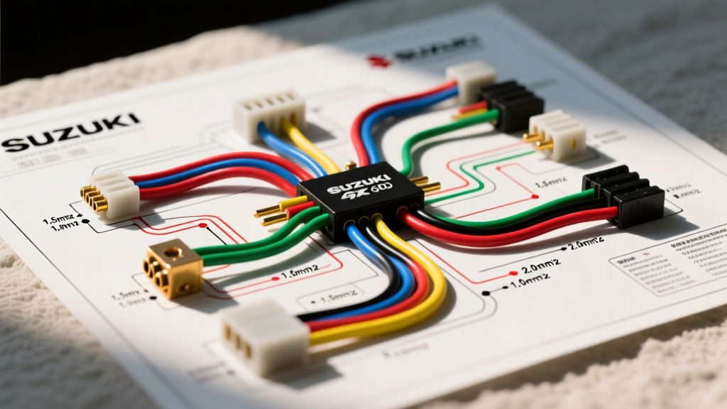
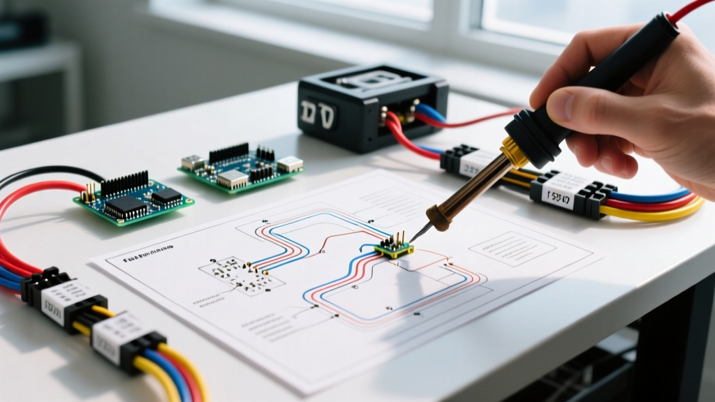
Working on a vehicle’s 12-volt electrical system is unforgiving. Unlike household AC wiring, automotive DC systems operate at low voltages but extremely high amperages. A loose ground or an undersized wire doesn't just trip a breaker; it can melt insulation, ignite surrounding plastics, and destroy the vehicle. According to the National Highway Traffic Safety Administration (NHTSA), electrical failures and short circuits remain a leading cause of highway vehicle fires. Before you cut, strip, or crimp a single wire, you need a roadmap. This is where free automotive electrical wiring diagrams become your most critical installation planning tool.
However, finding a diagram is only 10% of the battle. The real expertise lies in decoding the schematic, calculating voltage drop, selecting the correct SAE-rated components, and navigating the complexities of modern CAN-bus networks. This guide provides a comprehensive installation planning framework for DIYers and professional upfitters alike.
Sourcing Reliable Free Automotive Electrical Wiring Diagrams
The internet is flooded with spam sites claiming to offer 'free wiring diagrams' but delivering generic, useless 555-timer circuits or watermarked thumbnails. To plan a proper installation, you need factory-accurate schematics. Here is where professionals actually source them:
- AutoZone / AllDataDIY Backend: Many auto parts stores provide free access to AllData or Mitchell1 repair manuals via their in-store kiosks. You can view and photograph factory wiring diagrams for your specific make, model, and trim level.
- Enthusiast Forums (FSM Leaks): Factory Service Manuals (FSMs) are frequently archived on dedicated forums. Sites like NicoClub (Nissan), YotaTech (Toyota), and LS1Tech (GM) have massive repositories of PDF wiring diagrams uploaded by community members.
- OEM Upfitter Guides: If you are planning an install on a modern truck (e.g., Ford Super Duty, Ram 2500), manufacturers publish free 'Upfitter Body Builder Layout Books' on their fleet websites. These are goldmines for finding auxiliary power points and CAN-bus pinouts.
Expert Warning: Never trust a wiring diagram from an AI-generated content farm. Always cross-reference wire colors and pinouts with a multimeter before cutting into a factory harness. Factory diagrams represent the vehicle as it left the assembly line; previous owners may have spliced in unregulated modifications.
Decoding the Schematic: SAE vs. DIN Standards
When utilizing free automotive electrical wiring diagrams, you must first identify the standard being used. American and Asian vehicles typically use SAE (Society of Automotive Engineers) color codes, while European vehicles (BMW, VW, Volvo) often use DIN standards. The Society of Automotive Engineers (SAE) maintains these critical reference standards.
| Wire Color | Typical SAE Function | Typical DIN (Euro) Function |
|---|---|---|
| Red | 12V+ Constant (Battery) | Terminal 30 (Battery +) |
| Yellow | 12V+ Switched (Accessory/Ignition) | Terminal 15 (Ignition +) |
| Black | Ground (Chassis) | Terminal 31 (Ground) |
| Orange | Illumination / Dimmer | Terminal 58 (Lights) |
| Blue | Power Antenna / Amp Turn-on | Terminal 87 (Relay Output) |
The 4-Step Installation Planning Framework
Once you have your diagram, do not start pulling wire. Follow this four-step engineering framework to ensure your installation is safe, efficient, and reliable.
Step 1: Load Calculation & Alternator Headroom
Add up the maximum continuous amperage draw of your planned accessories. If you are installing a 1000W aftermarket amplifier, a 50W LED light bar, and a dual-battery isolator, your total draw could easily exceed 100 Amps. Check your vehicle's alternator rating. A stock 130A alternator with 80A of baseline vehicle load only leaves 50A of headroom. If your accessories exceed this, you must plan for a high-output alternator upgrade (e.g., Mechman 250A) before wiring begins.
Step 2: Wire Gauge Selection & Voltage Drop Math
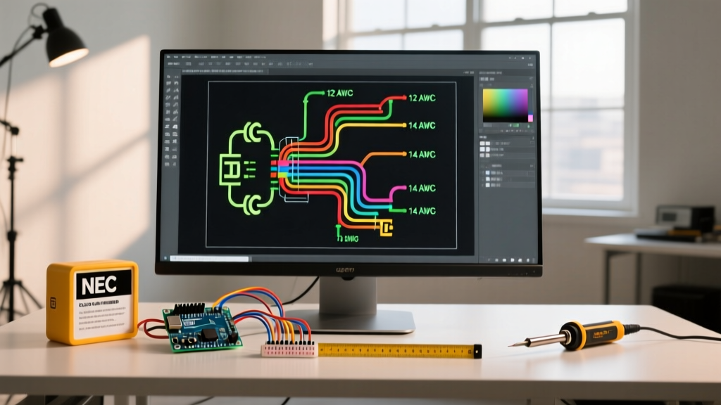
Automotive systems operate nominally at 12.8V (charging). A voltage drop of more than 3% (0.38V) can cause relays to chatter, lights to dim, and ECUs to throw low-voltage codes. Never use household THHN building wire; it is stranded poorly for vibration and uses insulation not rated for under-hood heat. Always use SAE J1128 rated wire, specifically TXL (thin-wall, 125°C) or GXL (150°C).
Example Calculation: You are running a 15-foot cable (30 feet total out-and-back) to a 40A winch solenoid. Using 8 AWG wire (0.628 milliohms/ft), the total resistance is 0.0188 ohms. At 40A, the voltage drop is V = I x R (40 x 0.0188 = 0.75V). A 0.75V drop on a 12.8V system is a 5.8% drop—unacceptable. You must upgrade to 4 AWG or 2 AWG welding cable for high-amperage, long-run applications.
Step 3: Fuse & Relay Placement Strategy
Free automotive electrical wiring diagrams will show you where the factory placed fuses, but for custom installs, you must adhere to the 'BFE' (Big Fuse Electronics) rule: The fuse must be placed within 18 inches of the power source. If your wire chafes against the firewall before the fuse, the entire cable becomes a glow plug. Use Blue Sea Systems ST Blade fuse blocks for centralized cabin accessories, and sealed ANL or Class-T fuses for under-hood high-amperage runs.
Step 4: Connector & Crimp Tooling Selection
Twist-ties and electrical tape are for amateurs. Plan your connector strategy based on the environment:
- Engine Bay (High Heat/Moisture): Use Deutsch DT series or Aptiv Metri-Pack 280 sealed connectors. Requires a specialized indent crimper (e.g., Glarks SN-28B).
- Cabin (Dry/Low Vibration): Standard open-barrel terminals with a ratcheting F-crimp tool (e.g., Titan 11120) and heat-shrink tubing.
Navigating Modern CAN-Bus and Multiplexed Networks
If you are using free automotive electrical wiring diagrams for a vehicle manufactured after 2015, you will inevitably encounter CAN-bus (Controller Area Network) and LIN-bus (Local Interconnect Network) lines. In older vehicles, a door-ajar switch was a simple ground wire. In modern vehicles, that same door switch communicates via a multiplexed digital signal to the Body Control Module (BCM).
The Failure Mode: If you tap a T-tap into a modern CAN-High or CAN-Low wire to trigger a relay for an alarm or remote start, you will introduce impedance into the network. This will cause cascading U-codes (communication faults), potentially putting the vehicle into limp mode or draining the battery via parasitic draw as modules fail to sleep.
The Solution: Plan your installation to use non-intrusive interface modules. Devices like the PAC TR-4 or iDatalink Maestro read the CAN-bus data digitally and output a clean, isolated 12V+ or ground trigger for your aftermarket accessories without splicing into the network wires.
Real-World Case Study: Planning a Dual-Battery & Winch Setup
Let’s apply this framework to a common 2026 off-road build: Installing a 12,000 lb winch and a dual-battery management system on a mid-size truck.
- Diagram Analysis: The factory FSM shows the main battery positive is located on the passenger side, but the winch mount is on the driver's side. The diagram also reveals a 150A mega-fuse on the main alternator feed.
- Component Sourcing: We select a Blue Sea Systems 9001e Battery Switch (rated for 300A continuous) and two Odyssey ODP-AGM12-1500 batteries.
- Wire Routing & Sizing: The run from the passenger battery to the driver's side winch solenoid is 8 feet. At a peak draw of 450A (winch stall current), we select 1/0 AWG (one-aught) fine-strand welding cable. Cost: ~$4.50 per foot.
- Circuit Protection: We install a 250A ANL fuse on the positive run immediately after the Blue Sea switch, and a 150A ANL fuse on the secondary battery feed to prevent backfeeding overloads.
- Total Material Cost Estimate: ~$285 for high-grade copper wire, lugs, heat shrink, and ANL fuse blocks (excluding the batteries and winch).
Expert FAQ: Troubleshooting the Install
Why does my custom relay click rapidly when the car is running?
This is almost always a voltage drop issue on the trigger wire. If you are pulling a 12V trigger from a factory tail light circuit, the PWM (Pulse Width Modulation) signaling used by modern BCMs to monitor bulb health will confuse a standard Bosch relay. Install a 1000µF capacitor across the relay coil pins (85 and 86) to smooth the PWM signal into a steady DC voltage.
Can I use the vehicle chassis as a ground return for high-amperage accessories?
For draws under 20A, a clean, paint-free chassis ground is acceptable. For high-amperage accessories (winches, amplifiers, inverters), you must run a dedicated ground wire back to the engine block or battery negative. The factory chassis straps are often undersized for aftermarket loads and will create a voltage differential, leading to erratic ECU behavior.
By leveraging free automotive electrical wiring diagrams not just as a picture, but as an engineering blueprint, you transform a risky guesswork project into a professional-grade installation. Always measure twice, crimp once, and fuse at the source.