
Mastering the Dual-Voltage RV Distribution System
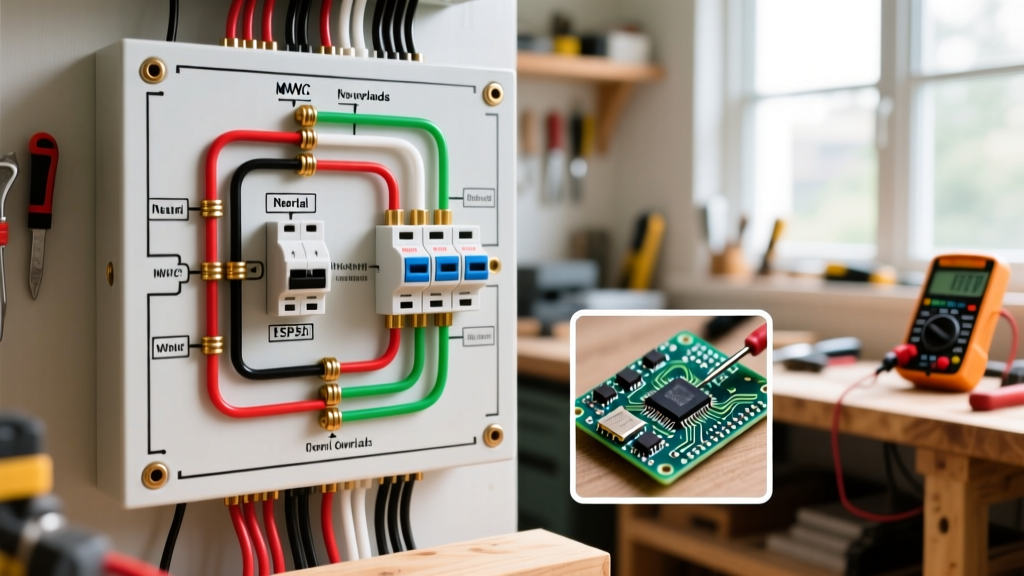
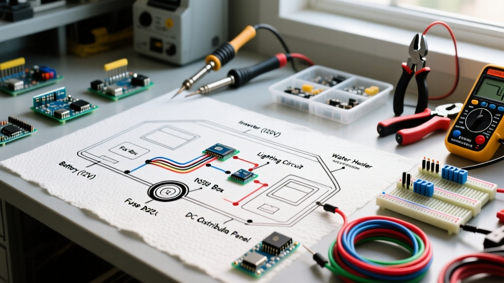
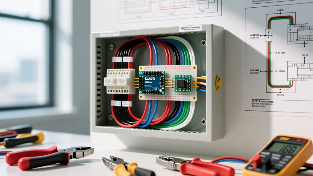
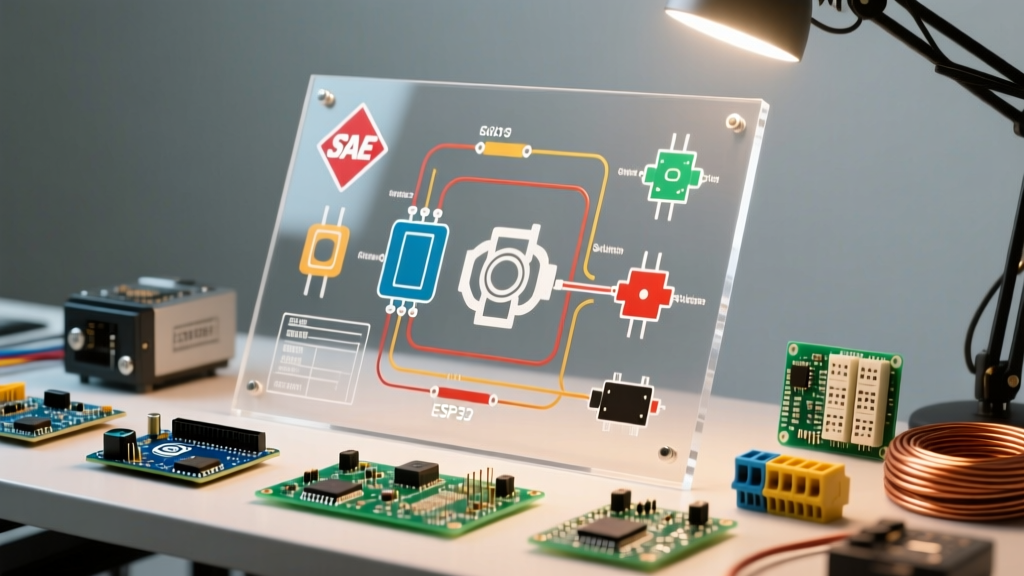
When upgrading, troubleshooting, or auditing your rig's power system, the travel trailer electrical wiring diagram is your foundational roadmap. Unlike residential homes that rely solely on 120V AC, travel trailers operate on a split architecture: a 120V AC system for heavy appliances and shore power, and a 12V DC system for lighting, water pumps, and control boards. The nerve center where these two systems intersect, divide, and are protected is the main distribution panel.
In 2026, with the mass adoption of LiFePO4 lithium battery banks and high-wattage inverter-chargers, understanding how to read and interpret the panel section of your wiring diagram is more critical than ever. Misinterpreting a breaker bus layout or ignoring DC fuse sizing can lead to catastrophic thermal events. This guide dissects the panel and breaker segment of your RV's schematic, providing exact hardware specifications, code-compliant wiring practices, and troubleshooting frameworks.
Deconstructing the Travel Trailer Electrical Wiring Diagram
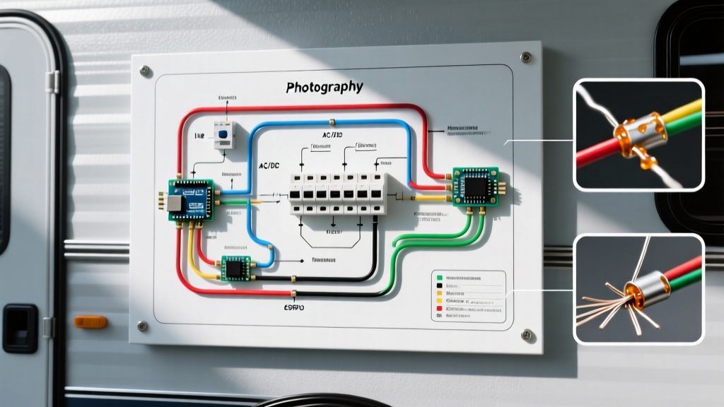
The panel section of your schematic is typically divided into three distinct zones. Understanding the symbology and routing between these zones is the first step to mastering RV electrical work.
1. The AC Distribution Breaker Box (120V)
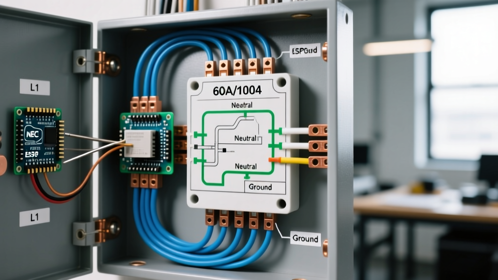
This section mirrors a residential sub-panel but is strictly governed by NFPA 1192 (Standard on Recreational Vehicles). The diagram will show the main 30A or 50A shore power feed entering a dual-pole or single-pole main breaker, which then feeds individual branch circuit breakers.
- Symbology: Look for rectangular blocks with a toggle line, labeled with amperage (e.g., "20A", "15A").
- Neutral & Ground: The diagram will explicitly route the AC neutral (white) to an isolated terminal bar and the bare copper ground to a separate chassis-bonded bus bar. Never bond neutral and ground in an RV sub-panel.
2. The DC Fuse Board (12V)
The DC side protects low-voltage circuits using ATO/ATC blade fuses. The wiring diagram will show the positive 12V feed originating from the battery bank or the DC output of the converter/charger, routing through a main 50A or 60A reverse-polarity fuse, before splitting into individual 10A, 15A, or 20A branch fuses.
3. The Converter/Charger Bridge
This is the most complex part of the schematic. The diagram illustrates how 120V AC enters the converter (e.g., a Progressive Dynamics or WFCO unit) to power the internal DC bus, while simultaneously sending 12V DC back to the fuse board to power the trailer's DC loads and charge the battery bank.
Breaker and Fuse Sizing Matrix
When verifying your travel trailer electrical wiring diagram against the physical panel, use this matrix to ensure circuits are properly protected. Undersized wires on oversized breakers are a leading cause of RV electrical fires.
| Circuit / Appliance | Voltage | Min. Wire Gauge (Stranded) | Protection Device | Typical Panel Slot |
|---|---|---|---|---|
| Roof Air Conditioner | 120V AC | 10 AWG | 30A AC Breaker | Slot 1 (Dedicated) |
| Microwave / GFCI Receptacles | 120V AC | 12 AWG | 20A AC Breaker | Slot 2 or 3 |
| Water Heater (AC Element) | 120V AC | 14 AWG | 15A AC Breaker | Slot 4 |
| Slide-Out Motor | 12V DC | 6 AWG (Direct) | Inline 40A Resettable | Bypasses DC Board |
| Interior LED Lighting | 12V DC | 14 AWG | 10A Blade Fuse | DC Slot 1-4 |
| Water Pump | 12V DC | 12 AWG | 15A Blade Fuse | DC Slot 5 |
| Awning Motor / Control | 12V DC | 12 AWG | 15A Blade Fuse | DC Slot 6 |
OEM Panel Hardware: WFCO vs. Progressive Dynamics
If your diagram calls for a panel replacement or you are building a custom teardrop trailer in 2026, you will likely choose between the two industry titans. Both offer integrated AC/DC power centers, but their internal bus bar layouts differ, which impacts how you route your wires.
WFCO WF-8955-PEC (55A Power Center)
Retailing around $165, the WFCO unit is ubiquitous in modern travel trailers. Its wiring diagram features a distinct "deck-mounted" design. The AC breakers are positioned vertically on the left, while the DC blade fuses sit horizontally on the right. Expert Note: The WFCO PEC series includes an integrated automatic transfer switch for generator hookups on specific models. If your schematic includes a generator relay, ensure you purchase the "-AD" or "-ATS" variant, not the standard PEC.
Progressive Dynamics PD4151KV (45A Power Center)
Priced at approximately $145, the Progressive Dynamics PD4100 series is favored by DIYers for its robust charge wizard and accessible terminal blocks. The diagram for the PD4151 shows the AC and DC sections physically separated by the converter module. Expert Note: The "V" in the PD4151KV denotes a vertically oriented DC fuse board, which is significantly easier to wire in tight under-bench compartments compared to horizontal layouts.
The Stranded Wire Mandate: A Critical Code Requirement
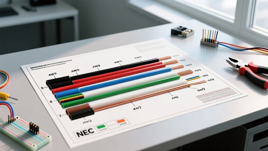
One of the most dangerous mistakes DIYers make when executing a travel trailer electrical wiring diagram is using residential solid-core Romex (NM-B) cable. This is strictly prohibited by NFPA 1192.
WARNING: Travel trailers experience constant high-frequency vibration and chassis flexing. Solid-core copper wire will work-harden, fatigue, and eventually snap inside the insulation, leading to arcing and hidden fires. You must use stranded copper wire (e.g., Southwire RV-specific stranded THHN or automotive GXL/SGT) for all AC and DC branch circuits.
When terminating stranded wire into standard Square D Homeline AC breakers or WFCO DC bus bars, you must use crimped ferrules or ring terminals. Never simply twist stranded wire and clamp it under a breaker screw; the strands will splay, reducing contact surface area and creating a high-resistance hot spot.
Tracing the Diagram: Step-by-Step Verification
When troubleshooting a dead circuit, do not blindly swap breakers. Use your schematic and a digital multimeter (like the Fluke 117) to trace the fault systematically.
- Verify Source Voltage: Measure across the main AC lugs (should read 115V-125V) and the main DC bus bars (should read 12.6V-14.4V depending on charge state).
- Isolate the Branch: Locate the specific breaker or fuse on the diagram. Pull the DC blade fuse or flip the AC breaker to OFF.
- Test for Continuity (Power Off): Disconnect the load wire from the breaker terminal. Place one multimeter probe on the breaker terminal screw and the other on the wire's destination point. A reading of near-zero ohms confirms the wire is intact.
- Check the Neutral/Ground Return: 80% of "dead" RV circuits are actually caused by a loose neutral wire on the AC bus bar or a corroded ground screw on the chassis. The wiring diagram will show exactly which neutral bus slot corresponds to your circuit.
2026 Upgrades: Integrating Inverter Sub-Panels
As RVers upgrade to 3000W+ inverter-chargers (like the Victron MultiPlus-II) to run residential fridges and induction cooktops off-grid, the standard travel trailer electrical wiring diagram must be heavily modified.
You cannot route a 3000W inverter's AC output through the standard OEM 30A main breaker. Instead, you must install a dedicated 50A AC sub-panel (such as a WFCO sub-panel or Blue Sea Systems AC breaker box). The new schematic must show an Automatic Transfer Switch (ATS) that seamlessly switches the AC branch circuits between Shore Power and Inverter Power, ensuring the inverter never back-feeds into the shore power pedestal.
Troubleshooting Edge Cases and Failure Modes
- Thermal Runaway on DC Bus Bars: If your diagram shows a 40A solar charge controller feeding the DC bus, but the bus bar is only rated for 30A continuous, the plastic housing will melt. Always verify the ampacity rating of the physical fuse board against the sum of all potential DC inputs (Converter + Solar).
- Converter Reverse Polarity: If you wire the DC output of a new converter backward, the main 30A reverse-polarity fuse on the DC board will instantly blow. This is a one-time protective measure. The diagram will highlight this specific fuse (usually a high-amp cartridge or large blade fuse located near the positive bus).
- Breaker Torque Specs: Loose breaker terminals cause arcing. Use an inch-pound torque screwdriver set to 20-25 in-lbs (verify with the breaker manufacturer's data sheet) when securing AC branch wires.
Final Thoughts on Schematic Literacy
A travel trailer electrical wiring diagram is not just a suggestion; it is a strict engineering document that ensures the safety of your rig. By understanding the distinct roles of the AC breaker box, the DC fuse board, and the converter bridge, you can confidently execute upgrades, diagnose complex faults, and ensure your electrical system remains compliant with modern RV safety standards. Always cross-reference your physical hardware with the schematic, use only stranded copper wire, and respect the ampacity limits of every terminal and bus bar.