
Decoding the Electric Fireplace Wiring Diagram for Modern Installations
Planning the installation of a modern built-in electric fireplace requires far more than simply finding an available wall outlet. High-end linear models, such as the Touchstone Sideline series or the Dimplex IgniteXL, draw substantial continuous current to power both their internal blowers and resistive heating elements. As a homeowner, contractor, or advanced DIYer, understanding the electric fireplace wiring diagram is the critical first step in ensuring a safe, code-compliant, and nuisance-free installation.
Unlike gas or wood-burning alternatives, electric fireplaces eliminate the need for venting, but they introduce strict electrical load requirements. In 2026, with the widespread adoption of high-wattage infrared quartz heating tubes and smart-home integration features, the electrical rough-in phase must be executed with precision. This installation planning guide breaks down the schematic requirements, circuit sizing mathematics, and National Electrical Code (NEC) mandates you need to know before framing your wall.
Anatomy of a Standard Electric Fireplace Wiring Diagram
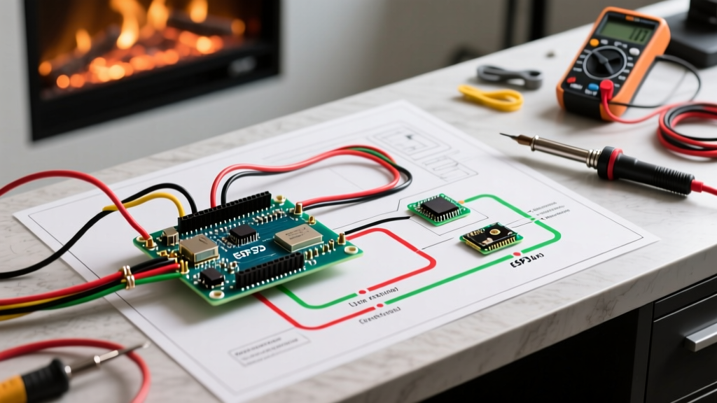
Most residential electric fireplaces operate on either a 120V or 240V circuit. When you pull the installation manual from the box, the wiring diagram will typically illustrate one of two configurations:
120V Hardwired Configuration (Standard)
- Line (L1): Black wire carrying 120V from the breaker panel.
- Neutral (N): White wire completing the circuit back to the panel.
- Ground (GND): Bare copper or green wire bonding the metal chassis to the grounding system.
Many 120V diagrams also show a separate pigtail for the blower motor and the heating element, which are wired in parallel internally but draw power simultaneously when the thermostat calls for heat.
240V Hardwired Configuration (High-Output)
For larger units (typically 60 inches or wider) designed to heat open-concept spaces, 240V models are required. These diagrams introduce a second hot leg:
- Line 1 (L1): Black wire (120V).
- Line 2 (L2): Red wire (120V), combining with L1 for 240V total.
- Neutral (N): White wire (often required for the 120V control board and LED flame motors, even if the heater is 240V).
- Ground (GND): Bare copper or green wire.
Expert Warning: Never assume a 240V electric fireplace operates without a neutral wire. The internal logic boards, LED flame projectors, and Wi-Fi modules almost always require 120V, which is derived from L1 and the Neutral. Always verify the specific schematic for your exact model number.
Load Calculation & The 80% Continuous Load Trap
The most common failure mode in electric fireplace installations is nuisance tripping. This occurs when installers ignore NEC Article 210.20(A) regarding continuous loads. A continuous load is defined as any load where the maximum current is expected to continue for three hours or more. During deep winter, a fireplace heater will easily run for three consecutive hours.
Under the NEC, branch circuit overcurrent devices (breakers) must be rated at no less than 125% of the continuous load. This means a standard 15-amp breaker can only safely handle a continuous load of 12 amps (1440 watts at 120V).
| Fireplace Wattage | Voltage | Amperage Draw | Min. Breaker Size | Required Wire Gauge (NM-B) | NEC Continuous Compliant? |
|---|---|---|---|---|---|
| 1500W | 120V | 12.5A | 20A | 12 AWG (12/2) | Yes (12.5A x 1.25 = 15.6A) |
| 2000W | 120V | 16.6A | 20A | 12 AWG (12/2) | Yes (16.6A x 1.25 = 20.7A)* |
| 3000W | 240V | 12.5A | 15A or 20A | 14/3 or 12/3 | Yes (on 20A breaker) |
| 4000W | 240V | 16.6A | 20A | 12 AWG (12/3) | Yes (16.6A x 1.25 = 20.7A)* |
*Note: For loads exceeding 20A continuous, a 30A breaker and 10 AWG wire are required. Always consult the manufacturer's specification sheet, as some 2000W units require a dedicated 20A circuit but explicitly state they cannot be used as a continuous 3-hour load without derating.
According to the National Fire Protection Association (NFPA) NEC 70, undersizing the breaker for a continuous heating load is a direct fire hazard and a guaranteed code violation. Always run 12/2 NM-B (Romex) on a dedicated 20A breaker for 120V hardwired units to provide a safe buffer.
AFCI and GFCI Code Requirements for 2026
When planning your circuit routing from the main panel to the fireplace junction box, you must select the correct breaker type based on the room's classification.
Arc-Fault Circuit Interrupter (AFCI)
NEC Article 210.12 mandates AFCI protection for 120V, 15A and 20A branch circuits in living rooms, family rooms, dens, and bedrooms. Since 90% of electric fireplaces are installed in these exact spaces, your dedicated 20A breaker must be a Combination-Type AFCI breaker. Standard thermal-magnetic breakers will fail the final electrical inspection.
Ground-Fault Circuit Interrupter (GFCI)
GFCI protection is generally not required for living room fireplaces. However, if you are installing an outdoor-rated electric fireplace on a covered patio, or a unit in a damp basement recreation area, NEC Article 210.8 requires GFCI protection. In these scenarios, use a dual-function (AFCI/GFCI) breaker or ensure the receptacle is GFCI protected if using a plug-in model.
Step-by-Step Rough-In and Framing Workflow
Proper physical planning prevents the need to tear open drywall later. Follow this sequence before the drywallers arrive:
- Frame the Alcove: Build your 2x4 or 2x6 stud wall according to the manufacturer's exact framing dimensions. Leave a minimum 1/2-inch clearance on the sides and top for airflow, unless the manual specifies zero-clearance to combustibles.
- Locate the Junction Box: Never mount the electrical junction box directly behind the fireplace unit. If the internal electronics fail, you will have to destroy the wall to access the wire nuts. Mount a standard metal or plastic old-work junction box in an adjacent stud bay, 12 to 18 inches above or below the fireplace framing, and drill a hole through the stud to feed the wires into the firebox cavity.
- Run the NM-B Cable: Pull your 12/2 or 12/3 cable from the panel to the junction box. Keep the cable at least 2 inches away from any HVAC ducting or recessed lighting cans that generate ambient heat.
- Install the Strain Relief: When feeding the cable into the fireplace's internal knock-out, ensure you use a proper Romex connector (strain relief clamp) to prevent the sharp metal edges of the firebox from slicing the wire insulation over time due to thermal expansion and vibration.
Smart Home Integration: Wiring for the Modern Home
In modern 2026 smart homes, homeowners frequently want to control their fireplace via voice commands or automated temperature routines. However, you cannot simply wire a standard smart switch to the main power line of an electric fireplace. Cutting power to the unit resets its internal logic board, Wi-Fi module, and thermostat settings.
The Correct Wiring Method: Look at your electric fireplace wiring diagram for a 'low voltage thermostat' or 'external control' terminal block. Many premium units feature a 2-wire dry contact or a 24V millivolt connection. You can wire a smart relay (such as a Shelly 1 or a specialized fireplace controller) to these low-voltage terminals. This allows the smart home system to trigger the fireplace's internal relay without cutting main power to the LED flames and Wi-Fi antenna.
Common Failure Modes and Troubleshooting
Even with a perfect wiring diagram, installations can experience issues. Here is how to troubleshoot the most common edge cases:
- Voltage Drop on Long Runs: If your main panel is in the basement and the fireplace is on a second-floor addition 120 feet away, a 12 AWG wire will experience voltage drop. A 120V circuit dropping below 114V (5% drop) will cause the blower motor to overheat and the heating element to underperform. For runs over 100 feet, upsize to 10 AWG wire.
- Shared Circuit Nuisance Tripping: If the fireplace is plugged into a shared living room circuit and a vacuum cleaner (10A) is turned on, the combined 22.5A draw will instantly trip a 20A breaker. Hardwiring on a dedicated circuit is the only permanent fix.
- Phantom LED Flickering: If the flame LEDs flicker when the heater kicks on, it indicates a loose neutral connection or severe voltage sag. Check the torque on the neutral bus bar in the main panel and ensure all wire nuts in the junction box are tightly secured with no exposed copper.
Final Safety and Inspection Checklist
Before closing up the wall with drywall or sliding the fireplace unit into the framing, complete this final verification. The U.S. Consumer Product Safety Commission (CPSC) emphasizes that improper grounding and loose connections are the leading causes of residential electrical fires.
- Verify ground continuity from the fireplace chassis to the main panel ground bus using a multimeter.
- Ensure the dedicated breaker is properly labeled in the panel directory (e.g., 'Living Room Fireplace - Dedicated 20A').
- Confirm that no combustible insulation (like fiberglass batts) is touching the rear or sides of the fireplace unit unless it is explicitly rated for zero-clearance to insulation.
- Test the AFCI breaker's physical 'Test' button to ensure the circuit trips correctly before energizing the fireplace for the first time.
By meticulously following the electric fireplace wiring diagram and respecting the continuous load mathematics outlined by the U.S. Department of Energy, you ensure your installation provides reliable, safe, and efficient supplemental heating for decades to come.