
Understanding the 1998 Dodge Ram 1500 Electrical Architecture
The 1998 Dodge Ram 1500, a cornerstone of the legendary BR platform, features a robust but highly specific 12V DC electrical system. Whether you are restoring a 5.2L Magnum V8 or upgrading the daily driver 5.9L, integrating modern aftermarket electronics requires a precise understanding of the factory harness. In this motor wiring tutorial, we break down the exact radio wiring diagram for 1998 Dodge Ram 1500 models, covering base audio systems, the complex Infinity premium sound edge cases, and the proper execution of automotive wire splicing according to industry standards.
Unlike modern vehicles that rely heavily on CAN-bus data networks for accessory power, the 1998 Ram utilizes a traditional analog switched-power and constant-power layout. However, the integration of the Chrysler Collision Detection (CCD) bus for the instrument cluster means that miswiring the illumination or dimmer circuits can result in catastrophic backfeeding, potentially frying the headlight switch rheostat or causing cluster communication faults.
The Core Radio Wiring Diagram for 1998 Dodge Ram 1500
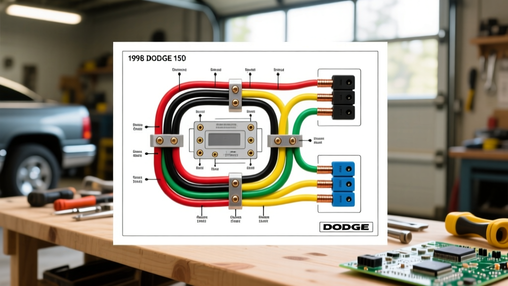
For a standard 1998 Dodge Ram 1500 without the factory Infinity amplifier, the radio connects via a dual-harness setup (typically a 7-pin and an 8-pin connector). Below is the definitive pinout and wire color chart for the factory base audio system.
| Wire Color | Function | Voltage / Signal | Recommended Gauge |
|---|---|---|---|
| Pink / White | 12V Constant (Memory) | 12V - 14.4V DC | 16 AWG |
| Red / White | 12V Switched (Ignition) | 12V (Run/Start) | 16 AWG |
| Black / Light Green | Chassis Ground | 0V (Return) | 16 AWG |
| Orange | Illumination | 12V (Headlights On) | 18 AWG |
| Orange / Black | Dimmer Control | 0V - 12V Variable | 18 AWG |
| Green | Left Front Speaker (+) | AC Audio Signal | 18 AWG |
| Green / Black | Left Front Speaker (-) | AC Audio Signal | 18 AWG |
| Purple | Right Front Speaker (+) | AC Audio Signal | 18 AWG |
| Purple / Black | Right Front Speaker (-) | AC Audio Signal | 18 AWG |
| Brown | Left Rear Speaker (+) | AC Audio Signal | 18 AWG |
| Brown / Black | Left Rear Speaker (-) | AC Audio Signal | 18 AWG |
| Dark Blue | Right Rear Speaker (+) | AC Audio Signal | 18 AWG |
| Dark Blue / Black | Right Rear Speaker (-) | AC Audio Signal | 18 AWG |
Expert Warning: Never connect the factory Orange/Black dimmer wire directly to a 12V constant source or an aftermarket head unit's 12V illumination output. The factory dimmer circuit is a variable resistance ground path. Backfeeding 12V into this line will instantly destroy the dimmer rheostat inside the factory headlight switch assembly.
The Infinity Premium Sound Edge Case
If your 1998 Ram 1500 is equipped with the factory Infinity premium sound system, the standard wiring diagram above will not yield audio. The Infinity system utilizes a 5-channel external amplifier (typically mounted under the passenger seat or behind the kick panel) and features low-level (RCA) pre-outs from the factory radio rather than high-level speaker wires.
Bypassing the Factory Infinity Amplifier
In 2026, the most reliable and cost-effective method for upgrading an Infinity-equipped '98 Ram is to bypass the factory amplifier entirely and run new 16 AWG speaker wire directly from the aftermarket head unit to the door speakers. While amplifier retention modules exist, they often introduce a high noise floor and cost upwards of $65. Bypassing the amp requires:
- Locating the Infinity amplifier and disconnecting the main power and speaker output harnesses.
- Tracing the speaker wires from the amplifier output plug back to the cabin wiring loom.
- Splicing your new 16 AWG speaker wires directly into the cabin-side harness, effectively removing the amplifier from the circuit.
- Ensuring the factory amp's 12V trigger wire is capped and insulated to prevent parasitic battery drain.
Motor Wiring Tutorial: Harness Adapters vs. Hardwiring
When executing automotive motor wiring, preserving the factory harness is paramount for future resale value and electrical safety. Cutting factory wires is a practice banned by professional installers. Instead, use a dedicated wiring harness adapter. Based on current 2026 market availability and pricing, here is how the top adapters compare:
- Metra 70-1004: The industry standard for base Chrysler 5x7 and 7x7 radios. Features pre-stripped, tinned copper pigtails. Price: ~$14.99.
- Scosche CR02B: A direct competitor to the Metra, featuring slightly thicker 16 AWG power pigtails which is excellent for high-draw modern multimedia units. Price: ~$12.50.
- PAC ROE-CHY: Best utilized if you are attempting to retain steering wheel controls (though rare on the '98 Ram, it is useful for later BR platform swaps). Price: ~$24.00.
Execution Standards: Crimping and Soldering in High-Vibration Environments
A truck like the 1998 Dodge Ram 1500 generates significant low-frequency vibration, especially with the Magnum V8 engines and solid front axles. Standard twist-and-tape wire splices will inevitably fail, leading to intermittent power loss or short circuits. According to the IPC/WHMA-A-620 Requirements and Acceptance for Cable and Wire Harness Assemblies, automotive wire terminations must withstand specific pull-test forces and environmental stress.
Furthermore, all primary automotive cable should meet the SAE J1128 Low Tension Primary Cable Standard for thermal and abrasion resistance. When joining your aftermarket head unit harness to the Metra or Scosche adapter, follow this strict protocol:
- Stripping: Strip exactly 3/8 inch of insulation from both wires using a precision wire stripper. Do not nick the copper strands, as this reduces the tensile strength and creates a hot-spot for resistance.
- Joining: Use adhesive-lined marine-grade heat shrink butt connectors (16-14 AWG for power, 22-18 AWG for speakers). Insert the wires so they meet in the center of the metal barrel.
- Crimping: Use a ratcheting crimping tool. The ratchet mechanism ensures the exact compression ratio is achieved, creating a cold-weld gas-tight seal that prevents oxidation.
- Sealing: Apply heat evenly until the adhesive lining melts and squeezes out the ends, completely waterproofing the connection against humidity and temperature swings.
For a comprehensive visual breakdown of these techniques, refer to the Crutchfield Car Stereo Installation Guide, which provides excellent step-by-step imagery for DIY installers.
Troubleshooting Common Failure Modes
Even with a perfect radio wiring diagram for 1998 Dodge Ram 1500, installers frequently encounter three specific electrical anomalies. Here is how to diagnose and resolve them using a digital multimeter (DMM).
1. Alternator Whine (Ground Loops)
Symptom: A high-pitched whining noise through the speakers that changes pitch with engine RPM.
Cause: A difference in ground potential between the radio chassis and the amplifier/speakers. In the '98 Ram, the factory ground point behind the dash is often corroded or shared with the HVAC blower motor.
Solution: Do not rely on the factory Black/Light Green ground wire if running high-current aftermarket head units. Run a dedicated 12 AWG ground wire from the radio's ground pin directly to a clean, unpainted metal bolt on the steel dash support frame. Verify continuity to the negative battery terminal; resistance should read less than 0.05 ohms.
2. Parasitic Battery Draw
Symptom: The truck battery is dead after sitting for 48 hours.
Cause: The Pink/White constant 12V wire is backfeeding power into the aftermarket radio's internal circuitry, or the factory Infinity amp trigger wire was left connected to a constant 12V source instead of a switched source.
Solution: Set your DMM to the 10A current setting. Pull the IOD (Ignition Off Draw) fuse located in the under-hood Power Distribution Center (PDC). If the draw drops below 50mA, the radio circuit is the culprit. Verify that the Red/White switched wire is strictly reading 0V when the key is removed.
3. Intermittent Display Shut-Off
Symptom: The aftermarket radio screen turns off when hitting bumps or turning the steering wheel.
Cause: The 1998 Ram's steering column wiring harness rubs against the lower dash panel, occasionally causing a momentary short on the ignition-switched circuit, or the crimp on the Red/White wire is failing due to vibration.
Solution: Inspect the main ignition feed at the steering column base. Re-crimp the Red/White adapter connection using the adhesive-lined heat shrink method detailed above, and secure the harness away from the column's moving tilt mechanism using nylon cable ties and split-loom tubing.
Final Integration and Testing
Before snapping the dash bezel back into place, perform a full functional test. Turn the key to the 'Run' position and verify the head unit powers on. Turn the key off and ensure the unit powers down completely. Turn on the headlights and verify the screen dims appropriately (if your aftermarket unit supports variable dimming and is wired to the Orange/Black wire via a step-down resistor, or simply toggles to the night-mode if wired to the Orange illumination wire). Finally, test all four speaker zones using the head unit's internal balance and fade controls to ensure no phase cancellation or crossed channels exist. By adhering strictly to this motor wiring tutorial and the exact radio wiring diagram for 1998 Dodge Ram 1500, you guarantee a factory-fit finish with professional-grade electrical reliability.