
Panel Integration: The Role of the Breaker in Pilot Light Circuits
When designing or retrofitting a commercial or residential control circuit, understanding the correct wiring diagram for switch with pilot light configurations is critical for both safety and functionality. Unlike standard single-pole toggles, a pilot light switch contains an integrated indicator lamp—typically a 120V neon bulb or an LED module—that illuminates only when the load is actively energized. From a panel and breaker perspective, this introduces unique circuit protection requirements, specific wire gauge calculations, and strict adherence to modern neutral conductor mandates.
At ElectricalFlux, we approach switch wiring not just from the device level, but from the origin point: the breaker panel. A properly protected pilot light circuit requires precise breaker sizing, accurate torque applications on panel lugs, and a deep understanding of how the switch interacts with modern AFCI (Arc-Fault Circuit Interrupter) protection. This guide provides a comprehensive, panel-to-load wiring framework for 120V AC pilot light switches, ensuring your installation meets the latest 2026 electrical standards.
Understanding the 120V Pilot Lamp Architecture
Before pulling wire from your panel, you must understand the internal architecture of the switch. A standard 120V pilot light switch (such as the widely used Leviton 5611-2W) operates its indicator lamp in parallel with the load. This means the switch requires three distinct electrical connections to function correctly:
- Line (Hot): The ungrounded conductor originating from the panel breaker.
- Load: The switched hot conductor traveling to the fixture or motor.
- Neutral: The grounded conductor required to complete the 120V circuit for the internal pilot lamp.
If you attempt to wire a 120V pilot light switch without a neutral wire at the switch box, the pilot lamp will either fail to illuminate or, in older incandescent setups, wire itself in series with the load, resulting in a dimly glowing lamp and reduced voltage to the fixture. Modern LED loads will simply fail to operate or cause the pilot lamp to flicker erratically.
Critical NEC Prerequisites: Neutral Conductors and Torque
When planning your panel-to-switch cable run, you must comply with the National Electrical Code (NEC) regarding switch loops and panel terminations. The National Fire Protection Association (NFPA 70) outlines strict rules that directly impact how you route cables for illuminated switches.
NEC Article 404.2(C) Neutral Conductor Requirement: Switches controlling line-to-neutral lighting loads must have a neutral conductor provided at the switch location. This is explicitly designed to accommodate electronic switches, timers, and illuminated pilot light switches that require a continuous 120V reference to power their internal circuitry.
Furthermore, when terminating the circuit at the breaker panel, NEC 110.14(D) requires that all electrical connections be torqued to the manufacturer's specified values. For standard 15A and 20A residential breakers (like the Eaton BR series), this typically requires a calibrated torque screwdriver set between 25 and 35 inch-pounds. Failing to torque panel lugs can lead to thermal expansion, arcing, and eventual nuisance tripping of the breaker, which is especially problematic for critical indicator circuits like sump pump or HVAC pilot light monitors.
Step-by-Step Wiring Diagram for Switch With Pilot Light
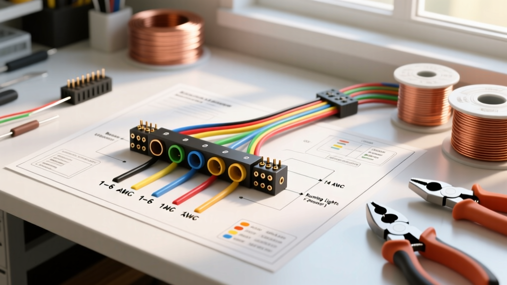
The following procedure outlines the physical wiring from the panel to the load for a standard 120V, single-pole pilot light switch. Always verify power is disconnected and use a non-contact voltage tester before beginning.
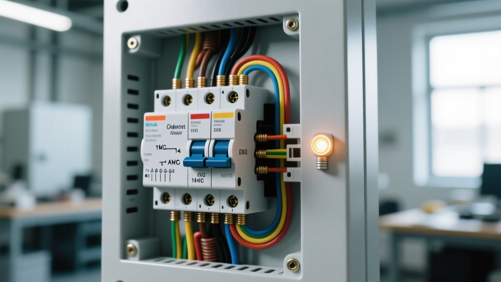
- Panel Termination: Route a 14/2 or 12/2 NM-B (Romex) cable from the panel to the switch box. Terminate the bare copper ground to the panel ground bus. Terminate the white neutral to the neutral bus bar. Terminate the black hot wire to the appropriate single-pole breaker (15A or 20A). Torque all lugs to spec.
- Switch Box Grounding: At the switch box, pigtail the bare copper ground wires together and attach them to the green grounding screw on the switch yoke and the metal box (if applicable).
- Line Connection: Connect the black (hot) wire from the panel to the brass 'LINE' terminal on the pilot light switch.
- Load Connection: Connect the black wire traveling to the load (fixture/motor) to the brass 'LOAD' terminal on the switch.
- Neutral Integration (The Critical Step): Bring the white neutral wire from the panel into the switch box. Connect it to the silver 'NEUTRAL' terminal on the switch. Note: You must also run a separate neutral wire from this switch box out to the load's junction box to complete the fixture's circuit.
- Load Termination: At the fixture, connect the load's black wire to the switch's load wire, and the fixture's white wire to the neutral wire originating from the switch box.
- Energize and Test: Turn on the breaker. The pilot light should remain OFF. Toggle the switch to the ON position; the pilot light and the connected load should illuminate simultaneously.
Circuit Protection Matrix: Wire Gauge and Breaker Sizing
Selecting the correct breaker and wire gauge is paramount. The pilot light itself draws negligible current (typically less than 0.5 watts or ~4 milliamps), so the circuit protection is sized entirely based on the connected load and the wire gauge used. Refer to the matrix below for standard 120V branch circuit configurations.
| Load Type | Max Continuous Watts | Max Amps | Required Wire Gauge | Breaker Size & Type |
|---|---|---|---|---|
| LED Lighting Array | 1,440W | 12A | 14 AWG Copper | 15A AFCI (e.g., Eaton BR115AF) |
| Heavy Duty Receptacle | 1,920W | 16A | 12 AWG Copper | 20A AFCI (e.g., Square D QO120CAFI) |
| Inductive Motor (1/2 HP) | 980W | 8.2A (FLA) | 14 AWG Copper | 15A HACR (HVAC Rated) Breaker |
| Commercial Heater | 1,500W | 12.5A | 12 AWG Copper | 20A Standard Thermal-Magnetic |
Note: For continuous loads (operating for 3 hours or more), the NEC requires the circuit to be derated to 80% of the breaker's capacity. A 15A breaker can only safely handle 12A of continuous draw.
Real-World Failure Modes and Edge Cases
Even with a perfect wiring diagram for switch with pilot light setups, field conditions can introduce complex failure modes. As a panel and breaker specialist, you must know how to diagnose these edge cases:
- AFCI Nuisance Tripping: Older neon-based pilot light switches can sometimes generate high-frequency electrical noise when the internal lamp strikes. This noise can be misinterpreted by modern Combination-Type AFCI breakers as a parallel arc fault, causing the breaker to trip immediately upon switch activation. Solution: Upgrade to modern LED-illuminated pilot switches (like the Leviton 5611-2W LED variant) which draw current smoothly and do not trigger AFCI algorithms.
- Ghosting (Dim Pilot Lamp When OFF): If the pilot light glows faintly when the switch is in the OFF position, you likely have induced voltage from adjacent parallel cables in a high-current conduit, or a leakage current issue from a solid-state relay downstream. Use a True-RMS digital multimeter to measure the voltage across the switch terminals when OFF. Readings between 10V and 40V indicate capacitive coupling. Solution: Install a 100k-ohm bleed resistor in parallel with the load to dissipate induced ghost voltages.
- Overheating Panel Bus Bars: If the pilot light switch is controlling a heavy inductive load (like a shop vacuum or air compressor), the initial inrush current can be 5 to 7 times the Full Load Amps (FLA). If the breaker is not HACR (Heating, Air Conditioning, and Refrigeration) rated, the magnetic trip mechanism may degrade over time, leading to hot panel bus bars. Always match the breaker's trip curve to the load's inrush profile.
2026 Component Selection and Cost Breakdown
When budgeting for a panel-to-load pilot light installation in 2026, material costs have stabilized, but the demand for smart-panel integration has shifted component preferences. Below is a realistic cost breakdown for a premium, code-compliant 15A pilot light circuit:
- Switch: Leviton 5611-2W (15A, 120V, LED Pilot, Ivory/White) — $14.50
- Breaker: Eaton BR115AF (15A Single Pole AFCI) — $48.00
- Wiring: 50ft of Southwire 14/2 NM-B Solid Copper — $22.00
- Tools: CDI Torque Screwdriver (10-50 in-lbs) for panel lugs — $65.00
Total material and specialized tool cost for a single high-end circuit hovers around $149.50. While cheaper, non-AFCI breakers and generic imported switches exist, utilizing UL-listed components from established manufacturers ensures compliance with OSHA electrical safety standards and local AHJ (Authority Having Jurisdiction) inspections.
Final Panel Integration Best Practices
A wiring diagram is only as effective as the physical execution at the panel. When adding a new pilot light switch circuit to an existing load center, always verify your panel's bus bar stab limit. Many older panels (such as Federal Pacific or Zinsco, which should be replaced immediately) or even modern 200A panels have strict limits on how many breakers can be physically installed, regardless of available physical space. Consult the panel's wiring diagram label inside the cover door to ensure you are not exceeding the maximum number of circuits or the physical stab capacity.
Furthermore, ensure your panel's neutral and ground bars are properly separated if this is a sub-panel. A pilot light switch circuit returning neutral current to a sub-panel where the neutral and ground are bonded will cause objectionable current to flow on the grounding conductors, violating NEC 250.142 and creating a severe shock hazard. For more detailed specifications on switchgear and breaker compatibility, refer to the National Electrical Manufacturers Association (NEMA) standards for enclosed switches and circuit protection devices.
By treating the pilot light switch not as an isolated device, but as the endpoint of a carefully calculated, panel-originated circuit, you ensure long-term reliability, code compliance, and optimal safety for any residential or commercial electrical system.