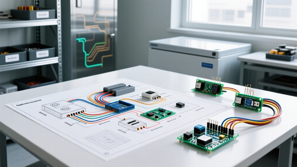

Decoding the Schematic: High-Voltage vs. Low-Voltage Loops
Commercial walk-in freezers are the financial backbone of food service and cold chain logistics. A single electrical fault can lead to tens of thousands of dollars in spoiled inventory. When a Bohn, Heatcraft, or Russell unit goes down, experienced technicians rely on the wiring diagram for walk in freezer schematics to isolate the fault rapidly. Unlike residential HVAC, commercial refrigeration involves complex 3-phase power, digital logic controllers, and multi-stage defrost circuits. As of 2026, the widespread adoption of Electronically Commuted Motors (ECMs) and A2L low-GWP refrigerants has further altered compressor electrical loads and control logic.
Before touching a multimeter, you must mentally divide the schematic into two distinct loops:
- High-Voltage Power Circuit (208/230V or 460V 3-Phase): This loop feeds the compressor contactor, evaporator fan contactors, and electric defrost heaters. It is protected by high-amperage fuses or HACR-rated circuit breakers.
- Low-Voltage Control Circuit (24VAC or 120VAC): Fed by a step-down transformer, this loop powers the digital thermostat (e.g., Dixell XR75CX or Johnson Controls A419), phase monitors, defrost timers, and contactor coils.
⚠️ CRITICAL SAFETY WARNING: Never assume the control circuit is dead just because the compressor is off. Many commercial walk-in schematics route 120VAC from a single phase (L1 to Neutral) directly to the defrost time clock and fan delay relays. Always verify zero energy state using a CAT III or CAT IV rated multimeter before opening the evaporator or condenser junction boxes.
Critical Component Matrix: Expected Values & Failure Modes
When tracing a wiring diagram for walk in freezer systems, technicians must know exactly what to expect at each node. The table below outlines standard 208/230V 3-phase system benchmarks and their most common failure modes.
| Component | Expected Voltage / Resistance | Common Failure Mode | Diagnostic Action |
|---|---|---|---|
| Phase Monitor (e.g., Macromatic SP-400) | 208-240V AC across L1-L2-L3 | Phase reversal or voltage sag dropping below 190V | Check LED fault codes; verify incoming utility voltage at the main disconnect. |
| Control Transformer (24VAC Secondary) | 208V Primary / 24VAC Secondary | Blown 3A automotive-style fuse on secondary side due to shorted contactor coil | Disconnect all 24V loads. Test resistance of evaporator and condenser fan contactor coils (expect 15-30 ohms). |
| Evaporator Fan Motors (PSC vs. ECM) | 208V (PSC) or 120V/277V (ECM) | ECM internal module failure due to moisture ingress; PSC run capacitor bulging | For ECM, check for 120VAC at the motor plug. If power is present but fan is dead, replace the motor module ($350-$500). |
| Defrost Termination Thermostat | Normally Closed (NC) below 55°F | Stuck open, forcing defrost to run on time-limit (e.g., 45 mins), causing massive temp spikes | Bypass termination thermostat temporarily to see if defrost contactor engages. Replace if circuit completes. |
| Crankcase Heater (Compressor) | 120V or 240V; draws 40-70W | Burned out element allowing liquid refrigerant migration and mechanical slugging | Measure resistance across heater leads. Infinite reading (OL) indicates a burned element. |
Advanced Troubleshooting: The Defrost Termination Edge Case
One of the most misunderstood circuits on any walk in freezer wiring diagram is the electric defrost sequence. Modern units utilize a 'demand defrost' or 'terminated defrost' logic to comply with stringent energy codes. The digital controller initiates the defrost cycle based on compressor run-time or a fixed interval (e.g., every 6 hours). However, the termination of the cycle relies on a bi-metal thermostat clamped directly to the evaporator coil.
The 'Time-Limit' Trap
If the defrost termination thermostat fails in the 'open' position, the controller will not receive the signal that the ice has melted. Instead, the defrost heaters will remain energized until the safety time-limit (usually 45 to 60 minutes) expires. This results in:
- Severe temperature spikes inside the freezer (often rising above 20°F).
- Melting ice that refreezes into a solid block at the bottom of the evaporator pan.
- Premature failure of the defrost heater elements due to running dry without ice to absorb the thermal load.
Pro-Tip: When consulting the schematic, locate the termination switch in series with the defrost contactor coil. If you measure 24VAC on the line side of the termination switch but 0VAC on the load side during an active defrost cycle, the switch has failed open. Replacement bi-metal thermostats (like the Johnson Controls A12AB-2C) typically cost under $25 and take 15 minutes to swap.
Compressor Circuit Diagnostics: Copeland Scroll ZF Series
The Copeland Scroll ZF series (e.g., ZF24K5E-TF5) is the industry standard for medium and low-temperature walk-in freezers. The wiring diagram for these compressors includes an internal thermistor and an external crankcase heater. A frequent edge-case failure involves the crankcase heater circuit.
The crankcase heater must remain energized whenever the compressor is off to prevent liquid refrigerant from migrating into the oil sump. If the heater burns out, or if the auxiliary contact on the compressor contactor fails to route power to the heater during the off-cycle, liquid refrigerant will pool in the crankcase. Upon the next startup, the compressor will attempt to pump incompressible liquid (slugging). This causes a massive, instantaneous spike in amperage that will either trip the breaker or blow the high-amp fuses. Always verify that the crankcase heater is warm to the touch after the unit has been off for at least 30 minutes.
Energy Efficiency and Regulatory Compliance
Electrical troubleshooting is not just about restoring function; it is about maintaining compliance and efficiency. According to the EPA ENERGY STAR Commercial Refrigeration guidelines, improperly calibrated defrost timers and failing ECM motors can increase a walk-in freezer's energy consumption by up to 30%. Furthermore, as the industry transitions to A2L refrigerants in 2026 to meet environmental mandates, electrical components must be properly sealed to prevent arc ignition of mildly flammable gases. For safety standards regarding lockout/tagout and arc flash hazards during these repairs, technicians must strictly adhere to OSHA's electrical safety standards and NFPA 70E protocols.
Frequently Asked Questions
Why does my walk-in freezer trip the breaker only during the defrost cycle?
Electric defrost heaters draw significant current (often 15-30 amps per phase). If the breaker trips exclusively during defrost, inspect the heater elements for physical swelling or grounding out against the metal evaporator pan. Use a megohmmeter (Megger) to test the insulation resistance of the heater elements; any reading below 1 megohm indicates a compromised element that is leaking current to ground.
Can I use a standard 24VAC HVAC transformer for a walk-in freezer control board?
While the voltage is the same, walk-in freezer environments demand transformers with specific moisture and vibration ratings. Furthermore, you must verify the VA (Volt-Ampere) rating. A standard 40VA residential transformer will quickly burn out if the walk-in schematic requires energizing multiple heavy-duty contactor coils and a defrost relay simultaneously. Always replace with a 75VA or 100VA Class 2 transformer as specified on the OEM wiring diagram.
What wire gauge should I use for replacing a 208V 3-phase compressor feed?
Wire gauge is dictated by the compressor's Minimum Circuit Ampacity (MCA) listed on the nameplate, not just the RLA. For a typical 5HP 208V 3-phase compressor with an MCA of 28A, the NFPA 70 (NEC) requires a minimum of 8 AWG THHN copper wire, protected by a 35A HACR breaker. Always consult the specific unit's wiring diagram and local codes before pulling new wire.