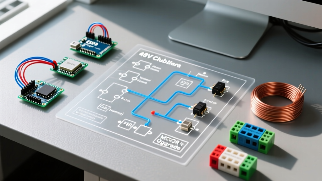

Anatomy of the 48-Volt Club Car DS Powertrain
Introduced in 1996, the 48-volt architecture fundamentally transformed the Club Car DS platform, delivering superior torque, extended range, and reduced amperage draw compared to the legacy 36V systems. Whether you are restoring a 1998 model or retrofitting a 2011 fleet cart, understanding the DS electric 48V Club Car wiring diagram is the first step toward reliable operation. Unlike modern Precedent or Onward models that utilize complex CAN-bus networks and IQ/Excel motor controllers, the 48V DS relies on a robust, easily serviceable analog-style high-current routing paired with a Curtis 1206E-5201 (or earlier 1206-5201) motor controller.
In this comprehensive vehicle-specific guide, we break down the exact routing, component pinouts, and diagnostic procedures for the 48 volt system. We will also cover 2026 lithium upgrade protocols, ensuring your cart remains relevant and efficient.
Core Wiring Routing: High-Current vs. Low-Current Circuits
The 48V DS electrical system is divided into two distinct circuits. Mixing these up is the most common cause of fried controllers and melted key switches.
1. The High-Current Traction Circuit
This circuit handles the massive amperage (up to 300A peak) required to move the vehicle. It utilizes heavy 2 AWG or 1/0 AWG welding cable.
- Battery Pack Positive (+): Routes from the positive terminal of the first battery in the series bank directly to the large input terminal on the main solenoid.
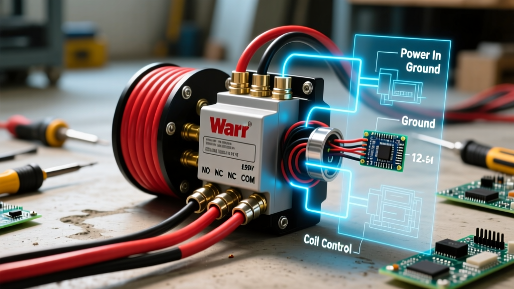
- Solenoid Output: The second large terminal on the solenoid routes to the B+ (Main Positive) stud on the Curtis 1206 controller.
- Controller to Motor: The controller's A1 and A2 terminals connect directly to the series-wound motor's armature. M- connects to the motor field, and B- routes back to the battery pack negative via a heavy-duty shunt.
2. The Low-Current Logic Circuit
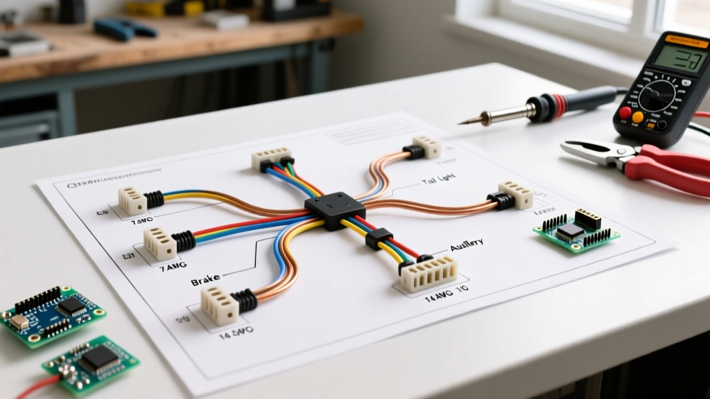
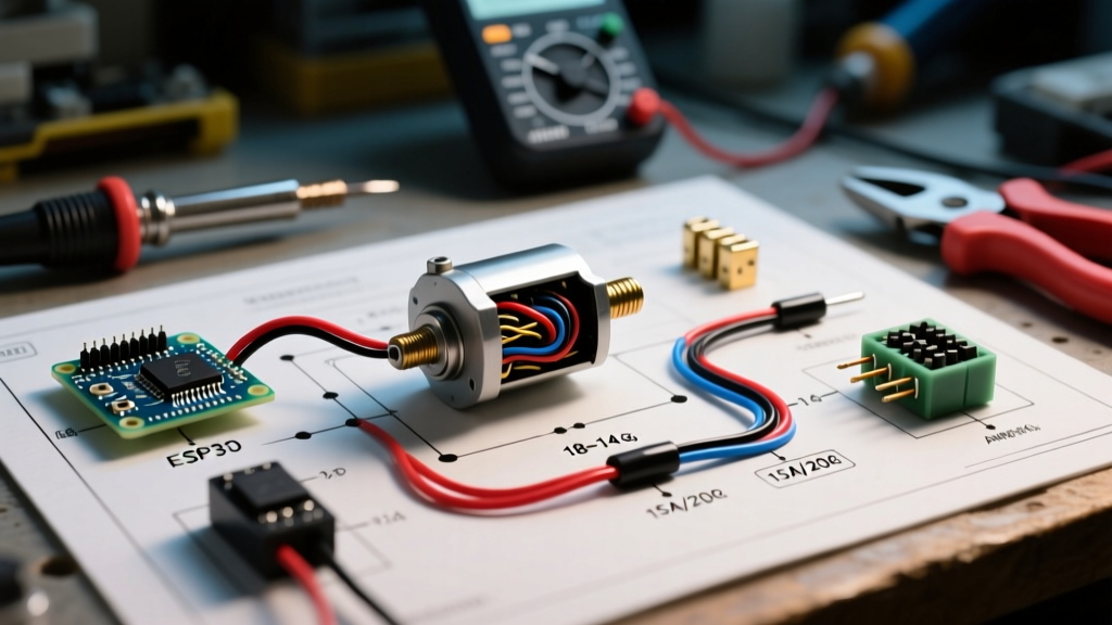
This 48V logic circuit activates the solenoid coil and powers the controller's internal microprocessor. It utilizes 14 AWG to 16 AWG wire and is protected by a 10A inline fuse.
- Key Switch Input: 48V enters the key switch. When turned 'ON', power exits to the F&R (Forward and Reverse) microswitches.
- F&R Switch Routing: Depending on the directional lever position, 48V is sent to either the Forward or Reverse input pin on the controller, while simultaneously completing the circuit to the solenoid's small activation coil.
- Precharge Circuit: Before the main solenoid engages, a 470-ohm, 2-watt precharge resistor (often paired with a diode) bleeds a small amount of current into the controller's internal capacitors. This prevents a massive voltage spike that could weld the solenoid contacts or blow the controller's internal MOSFETs upon initial startup.
48V Battery Bank Configurations & 2026 Matrix
The physical wiring diagram remains identical regardless of your battery chemistry, provided the nominal voltage is 48V (which actually reads around 50.4V to 51.2V at rest). However, the physical layout and maintenance requirements vary wildly. Below is a comparison of standard configurations available in the current market.
| Battery Configuration | 2026 Avg. Replacement Cost | Total Weight | Usable Capacity (Peukert Effect) | Maintenance Interval |
|---|---|---|---|---|
| 8x 6V Lead-Acid (e.g., Trojan T105) | $1,650 - $1,800 | 624 lbs | 50% (110Ah usable) | Monthly (Watering) |
| 6x 8V Lead-Acid (e.g., Trojan T875) | $1,450 - $1,600 | 552 lbs | 50% (85Ah usable) | Monthly (Watering) |
| 4x 12V Deep Cycle AGM | $1,100 - $1,300 | 280 lbs | 80% (70Ah usable) | None |
| 48V LiFePO4 Lithium (105Ah) | $1,900 - $2,400 | 85 lbs | 100% (105Ah usable) | None |
Critical Component Pinouts and Throttle Inputs
The transition years of the DS (1996–2011) saw two primary throttle input methods. Identifying which one your cart uses is vital when reading the wiring schematic.
The V-Glide Potentiometer (1996 - ~2008)
Early 48V DS models utilized a mechanical V-Glide assembly. A physical wiper arm moves across a resistive track. The controller expects a variable resistance reading between 0 ohms and 5,000 ohms (5kΩ). If the wiper track develops a dead spot due to carbon buildup, the Curtis controller will throw a HPD (High Pedal Disable) fault, refusing to engage the motor to prevent runaway acceleration.
The MCOR Upgrade (Motor Controller Optical Regulator)
Later models (and many modern restomods) use the MCOR, an optical sensor with no physical wiper track. It outputs a variable voltage signal (typically 0.8V to 3.2V) to the controller's J3 throttle harness. If you are upgrading a V-Glide cart to an MCOR, you must install a Curtis-compatible resistor network or swap the controller firmware to recognize the voltage input rather than the resistance input.
Step-by-Step Solenoid & Controller Troubleshooting
When a 48V DS refuses to move, the issue is almost always located in the logic activation circuit. Follow this exact diagnostic sequence using a digital multimeter (DMM).
- Verify the Tow/Run Switch: Located directly on the Curtis controller cover. Ensure it is fully pushed into the 'RUN' position. This microswitch completes the logic ground. If it fails, the controller is completely dead. Bypass it temporarily with a jumper wire to confirm.
- Check the 10A Logic Fuse: Trace the red/white wire from the positive battery terminal near the controller. Locate the inline 10A fuse. A blown fuse indicates a short in the key switch or F&R wiring harness.
- Test Solenoid Activation: Turn the key ON and press the throttle. You should hear a definitive 'click'. If no click occurs, place your DMM probes on the two small terminals of the solenoid. You should read full pack voltage (approx. 50V+). If you have voltage but no click, the solenoid coil is burned out (replace with an Albright SW200 or Trombetta equivalent).
- Voltage Drop Test (High Current Side): If the solenoid clicks but the cart doesn't move, place your DMM probes across the two LARGE terminals of the solenoid while pressing the throttle. The reading should drop to near 0.0V. If it remains at 48V, the internal contacts are carbon-fouled or welded open. Replace the solenoid.
Common 48V DS Failure Modes & Edge Cases
Safety Warning: Always adhere to NFPA National Electrical Code (NEC) guidelines for DC wiring. A short circuit in a 48V golf cart battery bank can deliver over 1,000 amps instantly, causing catastrophic arcing and fire. Always disconnect the main negative cable before working on the wiring harness.
- Melted Key Switches: Using the stock key switch to power high-draw accessories (like 48V-to-12V reducers for light bars) will melt the internal contacts. Always use an automotive relay triggered by the key switch for auxiliary loads.
- F&R Microswitch Misalignment: The Forward and Reverse housing contains two small microswitches. Over time, the plastic actuator cam wears down, failing to depress the switch fully. This results in a cart that only drives in one direction. Inspect the cam for physical grooving.
- Controller Capacitor Venting: If the precharge resistor (470-ohm) is missing or broken, the inrush current will blow the internal capacitors of the Curtis 1206. This is often accompanied by a loud pop and a venting of dielectric fluid from the controller's top seal.
2026 Lithium (LiFePO4) Upgrade Protocols
Upgrading a 48V DS to Lithium Iron Phosphate (LiFePO4) is the most popular modification in 2026, reducing cart weight by over 500 lbs and eliminating watering chores. However, you cannot simply drop a lithium battery in and use the stock lead-acid charger.
Lead-acid chargers utilize an equalization phase (pushing up to 58V+) that will trigger the BMS (Battery Management System) over-voltage protection on a lithium pack, permanently locking it out. You must install a lithium-specific charger. For OEM-style integration, the Lester Summit Series 2 with the Club Car 48V LiFePO4 charge profile (Part # 20950-10) is the industry standard. Furthermore, when wiring the BMS communication wires, ensure the main power cutoff relay is wired after the controller logic line, ensuring the BMS remains powered to accept the charger's handshake protocol. For exact harness adapters and OEM replacement components, consult the Buggies Unlimited Parts Catalog.
Frequently Asked Questions
Can I use four 12V car batteries to wire a 48V Club Car DS?
No. Standard automotive starting batteries are not designed for deep cycling. They will sulfation and fail within 3 to 6 months under golf cart loads. You must use deep-cycle marine/RV batteries at a minimum, though 6V or 8V golf-specific batteries (or LiFePO4) are highly recommended.
Where can I find the official factory schematics?
Original factory service manuals and wiring schematics for legacy models can often be sourced through Club Car Official Support or authorized legacy dealerships. Always verify the serial number prefix (e.g., 'A' for 1996, 'P' for 2005) as minor wiring revisions occurred throughout the DS production run.
Why does my cart jerk when taking off from a dead stop?
This is usually caused by a worn V-Glide potentiometer sending erratic resistance values to the Curtis controller, or a failing motor speed sensor (located on the rear of the motor). The controller attempts to adjust torque based on faulty feedback, resulting in a jerky acceleration curve.