
The Reality of Legacy Networks in 2026
Even as Cat 6A and fiber optics dominate new commercial builds in 2026, Category 5 and Cat 5e cabling remain the backbone of millions of legacy residential and small business networks. When these networks experience intermittent drops, slow throughput, or Power over Ethernet (PoE) failures, guessing the problem is a waste of time. Proper troubleshooting requires a systematic approach anchored by a precise wiring diagram for Cat 5 cable.
Unlike simple electrical wiring, network cabling operates at high frequencies (up to 100 MHz for Cat 5). At these frequencies, the physical geometry of the wire pairs matters just as much as electrical continuity. This guide will show you how to leverage standard wiring diagrams to identify complex faults that basic continuity testers completely miss.
The Core Wiring Diagrams: T568A vs. T568B Pinouts
Before diagnosing a fault, you must understand the baseline standard. The ANSI/TIA-568 standard defines two acceptable pinout configurations for 8P8C (RJ45) connectors. While T568B is more common in North American commercial settings, T568A is often mandated in government and residential contracts. A mismatch between the two ends of a cable creates a crossover cable, which modern Auto-MDIX switches can usually handle, but it remains a violation of structured cabling standards.
| Pin | T568A Color | T568B Color | Signal Function (10/100BASE-T) |
|---|---|---|---|
| 1 | White/Green | White/Orange | Transmit + (TX+) |
| 2 | Green | Orange | Transmit - (TX-) |
| 3 | White/Orange | White/Green | Receive + (RX+) |
| 4 | Blue | Blue | Unused (or PoE) |
| 5 | White/Blue | White/Blue | Unused (or PoE) |
| 6 | Orange | Green | Receive - (RX-) |
| 7 | White/Brown | White/Brown | Unused (or PoE) |
| 8 | Brown | Brown | Unused (or PoE) |
The 'Split Pair' Trap: Why Cheap Testers Lie
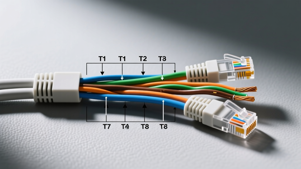
The most common and destructive fault in Cat 5 installations is the split pair. This occurs when an installer correctly maps the pins (e.g., Pin 1 to Pin 1, Pin 2 to Pin 2) but uses the wrong physical wire colors, breaking the twisted pair geometry.
Understanding the Physics of the Twist
According to guidelines published by BICSI, the twisting of the copper pairs is engineered to cancel out electromagnetic interference (EMI) and Near-End Crosstalk (NEXT). Pins 1 and 2 must be a twisted pair. Pins 3 and 6 must be a twisted pair.
If an installer wires Pin 3 to the Solid Blue wire and Pin 6 to the Solid Green wire, a basic $15 LED continuity tester will light up green, indicating a 'perfect' connection. However, because Pins 3 and 6 are no longer on the same physical twisted pair, the cable will suffer massive crosstalk at 100 MHz. The network will negotiate a link, but packet loss will cause severe latency and dropped connections.
Expert Insight: Never trust a simple continuity tester for data cabling. A split pair fault can only be detected by a dedicated wire mapper that measures crosstalk and pair mapping, not just DC resistance.
Step-by-Step Diagnostic Workflow
When a user reports a 'slow' or 'dropping' connection on a Cat 5 run, follow this diagnostic sequence using a professional wire mapper like the Klein Tools Scout Pro 3 (approx. $120) or the Fluke Networks MicroScanner PoE (approx. $480).
- Verify the Wire Map: Connect the main unit and the remote terminator. Check if the mapper flags 'Split Pairs', 'Reversed Pairs', or 'Transposed Pairs'. Compare the results directly against your T568A or T568B wiring diagram.
- Inspect the Untwist Length: Pull back the RJ45 boot. The ANSI/TIA-568 standard strictly mandates that the untwisted portion of the cable at the termination point must not exceed 13 mm (0.5 inches). Exceeding this destroys the cable's impedance and causes return loss.
- Check for Open or Short Circuits: An open circuit usually indicates a punched-down wire that didn't slice through the insulation on an IDC (Insulation Displacement Contact) keystone jack. A short indicates two adjacent pins are touching, often due to frayed copper strands inside the RJ45 plug.
- Measure Cable Length: Cat 5 is strictly limited to 100 meters (328 feet). Use the Time Domain Reflectometry (TDR) function on your tester to find the exact distance to a break or fault.
Advanced Troubleshooting: PoE on Legacy Cat 5
In 2026, running Power over Ethernet (PoE) to security cameras and Wi-Fi 6 access points over legacy Cat 5 is incredibly common. However, Cat 5 cable utilizes 24 AWG copper, which has higher DC resistance than the 23 AWG found in Cat 6.
Voltage Drop and Heat Dissipation
When pushing 802.3at (PoE+, 30W) over a 100-meter Cat 5 run, voltage drop becomes a critical factor. If your wiring diagram shows that you are only using two pairs (Pins 1,2 and 3,6) for data and relying on the phantom power on those same pairs, the 24 AWG wire may overheat or drop below the 37V minimum required by the powered device (PD).
- Solution: Ensure all four pairs (Pins 1,2,3,6 AND 4,5,7,8) are terminated. Modern PoE switches utilize 4-pair power delivery to distribute the current, halving the heat generated per wire and reducing voltage drop.
- Verification: Use a PoE-enabled tester to verify the voltage at the device end. If it reads below 44V under load, the cable run is too long or the copper quality is suspect (e.g., Copper Clad Aluminum / CCA).
Quick Reference Troubleshooting Matrix
Keep this matrix handy when interpreting your wire mapper results against the wiring diagram for Cat 5 cable.
| Tester Symptom | Probable Physical Cause | Diagram Check & Fix |
|---|---|---|
| Split Pair | Correct pins, wrong colors used (e.g., Pin 3 & 4 instead of 3 & 6) | Re-terminate both ends strictly following T568B/A color codes to ensure 3&6 share a physical twist. |
| Pair Reversed | Polarity swapped on a single pair (e.g., White/Orange on Pin 2, Solid Orange on Pin 1) | Check Pins 1 & 2. The 'White/Stripe' wire must always be on the odd pin (Pin 1). |
| Open Circuit (Pin 4,5,7,8) | Installer only punched down the data pairs and ignored the spare pairs. | Required for Gigabit Ethernet and 4-pair PoE. Punch down all 8 pins on the keystone jack. |
| High Return Loss | Cable untwisted too far back, or jacket stripped too deeply inside the plug. | Ensure untwist is < 13mm. The cable's outer jacket must extend fully into the rear of the RJ45 plug for strain relief. |
Final Thoughts on Copper Quality
Even with a perfect wiring diagram and flawless termination, Cat 5 cable manufactured with Copper Clad Aluminum (CCA) will fail modern troubleshooting tests. CCA has a higher attenuation rate and is highly prone to snapping during punch-down. As noted by the Telecommunications Industry Association (TIA), CCA does not meet the physical or electrical requirements for any Category of twisted-pair cabling. If your TDR length measurements are wildly inaccurate (e.g., the tester thinks a 50-meter cable is 80 meters long), you are likely dealing with CCA, as the tester's Nominal Velocity of Propagation (NVP) is calibrated for pure copper. In these cases, replacement with pure bare copper Cat 5e or Cat 6 is the only viable solution.
For comprehensive testing standards and certification parameters, network professionals should regularly consult the testing guidelines provided by Fluke Networks to ensure their field equipment is calibrated to the latest firmware and TIA standard revisions.