
Why Ditch Paper Schematics for Motor Control?
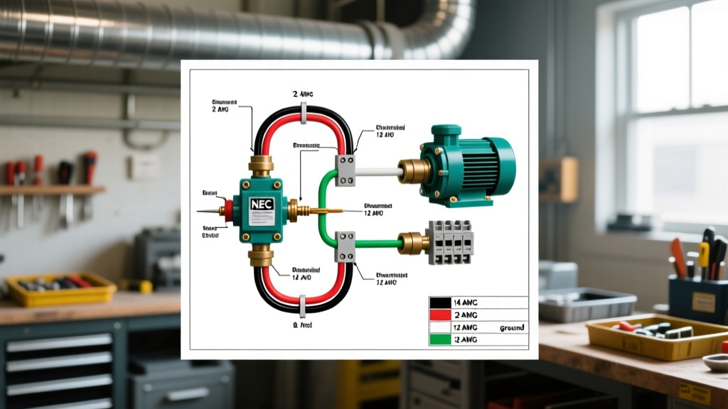
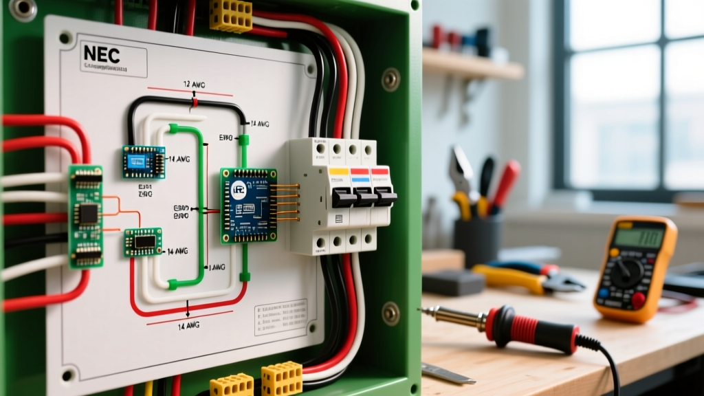
When wiring complex 3-phase induction motors, Variable Frequency Drives (VFDs), or reduced-voltage starters, relying on static paper schematics is a recipe for costly errors. In 2026, the modern industrial electrician and control panel builder relies on a dedicated electrical wiring diagram app to design, simulate, and troubleshoot motor circuits dynamically. Digital tools allow you to instantly calculate voltage drop, simulate logic states before applying 480V power, and ensure compliance with the latest NFPA 70 (NEC) Article 430 standards.
Whether you are in the field tracing a faulty thermal overload relay or in the shop drafting a NEMA-compliant control panel, selecting the right software is critical. Below, we break down the top applications for motor wiring, complete with real-world pricing, feature sets, and a step-by-step tutorial for simulating a Star-Delta starter.
Top Electrical Wiring Diagram Apps for Motor Projects
Not all schematic tools are built for heavy industrial motor control. While generic CAD software can draw lines, a specialized motor wiring app understands the difference between a NEMA and IEC contactor symbol, and automatically generates bill of materials (BOM) and wire lists.
| App Name | Platform | Best Use Case | 2026 Pricing | Motor Symbol Library |
|---|---|---|---|---|
| QElectroTech | Windows, Mac, Linux | Open-source IEC/NEMA panel schematics | Free (Open Source) | Extensive (Customizable) |
| Electrical Wiring Pro | iOS, Android | Field calculations, wire sizing, NEC lookups | $4.99 (iOS) / $3.99 (Android) | Reference only (No drafting) |
| iCircuit | iOS, Android, PC | Real-time logic simulation and VFD testing | $9.99 (Mobile) / $24.99 (PC) | Functional logic blocks |
| AutoCAD Electrical | Windows | Enterprise-level automated panel design | $1,955 / year | Massive (JIC/IEC compliant) |
1. QElectroTech (Best Open-Source for IEC/NEMA Schematics)
For control panel builders who need to draft intricate motor starter circuits without the enterprise price tag, QElectroTech is the undisputed champion. It natively supports IEC 60617 and NEMA ICS 19 symbol libraries. If you are wiring a 50HP motor and need to map out the auxiliary contacts on a Schneider Electric TeSys D-line contactor, QElectroTech allows you to link the coil to its specific NO/NC contacts across multiple schematic pages automatically.
2. Electrical Wiring Pro (Best Mobile App for Field Techs)
While it does not draw schematics, this app is an indispensable companion for the physical wiring phase. According to the NFPA 70 National Electrical Code, motor branch circuits require specific overcurrent protection sizing (often 250% of the Full Load Amps for inverse-time breakers). Electrical Wiring Pro calculates this instantly. You input a 480V, 30HP motor with a 1.15 service factor, and the app immediately outputs the required THHN copper wire gauge (typically 4 AWG) and the maximum standard breaker size (110A), saving you from flipping through Chapter 9 tables in the dirt.
3. iCircuit (Best for Simulating Motor Logic & VFDs)
iCircuit bridges the gap between drawing and testing. Its real-time simulation engine is perfect for testing motor control logic, such as interlocking forward and reverse contactors to prevent a dead short. You can wire up virtual pushbuttons, timers, and motor loads to watch the current flow and verify that your electrical interlocks hold up before you wire the physical 24VDC control circuit.
Step-by-Step: Designing a VFD Control Circuit in QElectroTech
Let us apply these tools to a common industrial scenario: wiring the control circuit for an Allen-Bradley PowerFlex 525 VFD controlling a 10HP centrifugal pump. We will use QElectroTech to draft the 120VAC control schematic.
- Establish the Control Voltage Source: Begin by placing a 480V to 120V step-down control transformer. Add primary and secondary fusing (e.g., 2A primary, 4A secondary) as dictated by NEC Article 430.72.
- Draft the Safety Chain: Wire an E-Stop (Emergency Stop) mushroom button in series with a safety relay. This ensures that hitting the E-Stop drops the VFD's digital input, triggering a Category 0 stop.
- Map the VFD Terminals: The PowerFlex 525 uses specific terminal designations. Draw the VFD I/O block. Connect your 'Start' momentary pushbutton to Digital Input 01 (Terminal 01) and your 'Stop' maintained switch to Digital Input 02 (Terminal 02).
- Implement Sink/Source Logic: The 525 defaults to Sinking logic. Ensure your 24VDC common (Terminal 04) is wired correctly to the pushbutton commons, and the +24VDC (Terminal 11) feeds the switch inputs. Miswiring this is the number one cause of blown opto-isolators in the field.
- Add Status Indicators: Wire the VFD Relay Output 0 (Terminals R1, R2) to a green 'Run' pilot light, and the Fault Relay (Terminals R3, R4) to a red 'Fault' indicator.
Pro Tip: Always route your 120VAC control wiring and 24VDC signal wiring in separate physical wire ducts inside the panel. Crossing high-voltage AC lines with low-voltage analog speed reference wires (0-10V) will induce Electromagnetic Interference (EMI), causing erratic motor speeds.
Simulating a Star-Delta Starter Transition with iCircuit
Reduced voltage starting is critical for high-inertia loads like large air compressors to prevent severe voltage dips on the plant grid. The Star-Delta (Wye-Delta) starter is the most cost-effective method, but timing the transition is notoriously tricky.
Using iCircuit on a tablet, you can simulate the exact transition logic before programming the physical timer relay (such as a Schneider Electric RE17RMMU).
- The Star Phase: When the Start button is pressed, the Main contactor and Star contactor engage. The motor windings are connected in a Wye configuration, reducing the starting voltage to 57% (1/√3) and starting current to 33% of Direct-On-Line (DOL).
- The Open Transition Delay: This is where most electricians fail. When the timer expires, the Star contactor must drop out before the Delta contactor pulls in. If they overlap for even 20 milliseconds, you create a direct phase-to-phase short circuit. In iCircuit, set an off-delay timer of 50ms to 100ms between the Star dropout and Delta pull-in.
- The Delta Phase: The Delta contactor engages, applying full line voltage (e.g., 480V) to the windings. The motor runs at full torque.
By simulating this in the app, you can visually verify that the mechanical interlock (a physical plastic block between the Star and Delta contactors) is backed up by a flawless electrical interlock in your schematic.
Common Motor Wiring App Mistakes & Edge Cases
Even the best electrical wiring diagram app cannot save you from fundamental engineering oversights. Watch out for these common pitfalls when transitioning from digital design to physical panel wiring:
Ignoring the 1.15 Service Factor
Many apps default to standard Full Load Amps (FLA) for thermal overload relay sizing. However, if your motor nameplate lists a 1.15 Service Factor (SF), the U.S. Department of Energy's motor efficiency guidelines and NEC 430.32 allow you to size the overload heater or electronic trip setting at 125% of the SF current, not the standard FLA. Failing to adjust this in your app's BOM will result in nuisance tripping when the motor runs hot.
VFD Output Contactors
Never place a standard contactor on the output side (load side) of a VFD in your schematic unless it is specifically interlocked to only open when the VFD is in a zero-output state. Opening a contactor while the VFD is actively switching PWM (Pulse Width Modulation) waveforms will cause massive voltage spikes due to inductive kickback, instantly destroying the VFD's IGBT power modules.
Sourcing Real-World Motor Data for Your Apps
To make your digital schematics accurate, you must feed them real-world data. When using tools like AutoCAD Electrical or QElectroTech, ensure you are downloading manufacturer-specific macro files. Companies like ABB, Siemens, and Rockwell Automation provide free, pre-wired CAD blocks for their motor protection circuit breakers (MPCBs) and soft starters.
Furthermore, always cross-reference your app's wire-sizing outputs with the latest edition of the NEC and local amendments. For comprehensive standards on motor manufacturing and naming conventions, refer to the National Electrical Manufacturers Association (NEMA) standards portal. By combining the computational power of a modern electrical wiring diagram app with rigorous adherence to industry standards, you ensure your motor control systems are safe, efficient, and built to last.