
Why Wiring Diagrams Are Your Best Troubleshooting Tool
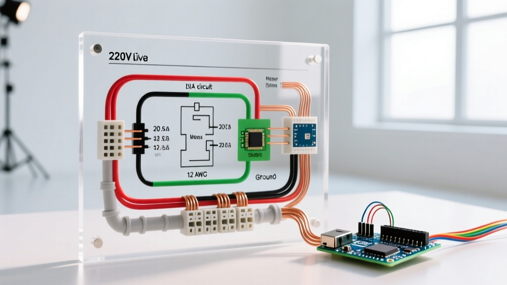
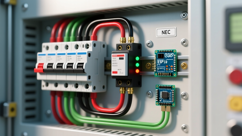
When a circuit goes dead or a breaker repeatedly trips, guessing which wire goes where is a recipe for disaster. While the term electrical wiring fuse box is often used colloquially to describe modern circuit breaker panels (consumer units), the troubleshooting principles remain the same whether you are dealing with legacy Edison-base fuses or a modern 200-amp Square D Homeline panel. A schematic or wiring diagram transforms a chaotic nest of Romex cables into a logical map. By cross-referencing your physical panel with its diagram, you can isolate faults, identify multi-wire branch circuits (MWBCs), and verify neutral-to-ground bonds without blindly pulling wires.
In this guide, we will break down how to read panel schedules and wiring diagrams, use a multimeter to trace faults, and identify common failure modes in residential electrical systems as of 2026.
Decoding the Electrical Wiring Fuse Box Schematic
Before touching a screwdriver, you must understand the visual language of your panel's documentation. Most modern panels, such as the Eaton BR series or Siemens PN Series, include a schematic inside the panel door. Here is what you need to look for:
- Main Bus Bars (Hot Legs): Represented by two thick vertical lines. In a standard US 120/240V split-phase system, these are Leg A (L1) and Leg B (L2), each carrying 120V relative to ground, and 240V phase-to-phase.
- Neutral and Ground Lugs: Often depicted as horizontal bars at the top or bottom. In a main service panel, the neutral and ground bars are bonded. In a subpanel, the diagram will show them as physically isolated.
- Branch Circuit Nodes: Each breaker slot is mapped to a specific circuit number. Odd numbers typically land on L1, and even numbers land on L2.
- MWBC Indicators: If your diagram shows a handle-tie symbol or a shared neutral line connecting two adjacent breakers, you have a Multi-Wire Branch Circuit. This is critical for troubleshooting, as turning off only one breaker leaves the shared neutral energized.
Expert Insight: Never rely solely on the handwritten panel schedule taped to the door. Previous homeowners often mislabel circuits. Always use the factory schematic to understand the architecture of the panel, and verify live circuits with a tester.
Essential Tools for Diagram-Guided Diagnostics
To effectively troubleshoot an electrical wiring fuse box using diagrams, you need precise instrumentation. Relying on cheap voltage pens can lead to false positives due to phantom voltage.
| Tool | Model Recommendation | Approx. Cost (2026) | Primary Use |
|---|---|---|---|
| True-RMS Multimeter | Fluke 117 or Klein Tools MM700 | $160 - $220 | Measuring exact voltage drops, testing continuity, and identifying shared neutrals. |
| Non-Contact Voltage Tester | Klein Tools NCVT-3 | $35 - $45 | Initial safety verification before touching any bus bar or terminal. |
| Circuit Breaker Finder | Extech CB10 | $40 - $55 | Mapping unlabeled branch circuits from the receptacle back to the panel diagram. |
| Clamp Meter | Fluke 325 | $180 - $210 | Measuring amp draw on a specific hot leg without breaking the circuit. |
Step-by-Step Troubleshooting: Tracing a Dead Circuit
Let's walk through a real-world scenario: A 15-amp AFCI breaker protecting a bedroom circuit keeps tripping, and resetting it fails. Here is how to use the diagram and your tools to find the fault.
Step 1: Verify the Panel Architecture
Check the diagram to confirm the breaker type. Modern 2026 NEC updates mandate Combination-Type AFCI protection for almost all living spaces. If your diagram shows a standard thermal-magnetic breaker but the physical unit is an AFCI (e.g., Square D HOM115CAFI), note that AFCIs detect parallel arcing, not just overloads. The diagnostic LED on the breaker will blink a specific code (e.g., 2 blinks for an arc fault, 3 for a ground fault).
Step 2: Isolate the Branch Circuit
Turn off the main breaker. Warning: The service entrance cables above the main breaker remain live. According to OSHA electrical safety guidelines, always treat the main lugs as energized unless physically disconnected by the utility. Use your NCVT-3 to verify the branch breaker terminals are dead before removing the panel cover.
Step 3: Test for Shorts and Ground Faults
Set your Fluke 117 to the continuity/ohms setting. Disconnect the hot (black) and neutral (white) wires from the breaker and neutral bar. Place one probe on the hot wire and the other on the ground bar. A reading of 'OL' (Open Loop) is good. A reading near 0.0 ohms indicates a dead short to ground, explaining the trip. Consult your diagram to trace where this specific circuit routes (e.g., Bedroom 1 receptacles) to begin physical inspection.
Step 4: The Shared Neutral Trap (MWBC)
If your diagram indicates an MWBC, you must turn off both handle-tied breakers. If you only turn off one, the return current from the active leg will travel back through the shared neutral, which can shock you when you disconnect the neutral wire in the panel. Always verify the diagram for shared neutrals before servicing.
Common Faults and Diagram Mapping
Use this matrix to cross-reference your physical symptoms with the logical nodes on your electrical wiring fuse box diagram.
| Symptom | Diagram Node to Check | Multimeter Reading | Likely Failure Mode |
|---|---|---|---|
| Breaker trips instantly upon reset | Branch Hot to Ground Bar | 0.0 Ohms (Continuity) | Dead short (e.g., nail through Romex, melted wire nut). |
| Breaker trips after 10-15 minutes | Branch Hot Leg (Clamp Meter) | > 15 Amps on a 15A circuit | Thermal overload. Too many appliances on one node. |
| 120V Receptacle reads 90V-105V | L1/L2 Bus Bar to Neutral | 120V at panel, 95V at receptacle | Voltage drop due to undersized wire (e.g., 14 AWG on a long run) or loose neutral connection at the lug. |
| Neutral Bar shows scorch marks | Neutral Lug / Main Bonding Jumper | High resistance (> 1 Ohm) across bond | Loose neutral connection causing arcing. Requires immediate torqueing to manufacturer specs (usually 20-40 in-lbs). |
Upgrading and Code Compliance (2026 Context)
If your troubleshooting reveals that your electrical wiring fuse box is an actual legacy fuse panel (e.g., a 60-amp Federal Pacific or Zinsco board with glass fuses), no amount of diagram tracing will make it safe. These panels are notorious for bus bar degradation and failure to trip during faults. The National Fire Protection Association (NFPA) and the National Electrical Code (NEC) strictly enforce modern safety standards.
As of 2026, upgrading to a 200-amp panel with plug-on neutral AFCI/GFCI breakers (like the Eaton BRP series) costs between $2,200 and $3,800 depending on regional labor rates and service entrance upgrades. The Consumer Product Safety Commission (CPSC) strongly recommends replacing any panel that uses fuses or is manufactured by known defective brands (FPE, Zinsco, Challenger) due to severe fire risks.
When to Call a Licensed Electrician
While DIY enthusiasts can safely use diagrams to map circuits, test continuity, and identify faulty receptacles, you should never attempt the following without a licensed professional:
- Removing the main breaker to replace bus bars.
- Upgrading the service entrance cables from the utility pole.
- Installing a subpanel that requires calculating continuous vs. non-continuous load derating.
- Working inside the panel if you detect a burning smell, buzzing sounds, or visible arcing scars on the hot bus bars.
Final Thoughts on Schematic Troubleshooting
An electrical wiring fuse box diagram is more than just a sticker on a metal door; it is the foundational blueprint of your home's power distribution. By combining the logical mapping of the schematic with the empirical data from a True-RMS multimeter, you can move past guesswork and accurately diagnose everything from phantom voltage drops to complex arc faults. Always prioritize safety, respect the main service lugs, and ensure your panel meets current NEC standards to protect your home and family.