
The Reality of 220V vs. 240V Nominal Voltage
When working with heavy-duty workshop equipment like 60-gallon air compressors, 10-inch cabinet saws, or industrial lathes, you will frequently encounter the search for a 220v electric motor wiring diagram. However, before making any terminations, it is crucial to understand modern voltage standards. Under the ANSI C84.1 standard, the nominal voltage delivered by North American utilities is 240V (split-phase). Legacy terminology, older motor nameplates, and colloquial workshop jargon still heavily rely on the terms '220V' or '230V'. For the purposes of wiring and overcurrent protection, a motor rated for 230V on its nameplate is designed to operate safely on a standard 240V residential or commercial supply, accounting for a standard +5% to -10% voltage drop tolerance.
In 2026, premium efficiency motors, such as the WEG W22 series or the Leeson C145T17FB60B, dominate the market. These single-phase induction motors typically range from 2HP to 5HP for standard DIY and light-industrial applications, drawing significant current that mandates strict adherence to wiring diagrams and National Electrical Code (NEC) Article 430 guidelines.
Decoding the Motor Nameplate: Your Primary Reference
Never rely on a generic internet diagram without cross-referencing the specific nameplate data of your motor. The nameplate provides the exact Full Load Amps (FLA), Service Factor (SF), and terminal configuration. For example, a 3HP, 230V single-phase motor typically has an FLA of 17.0 Amps. If the motor has a Service Factor of 1.15, the Service Factor Amps (SFA) will be roughly 19.5 Amps. This SFA value is critical when setting the dial on an adjustable thermal overload relay inside your motor starter.
Expert Insight: Always verify the 'Insulation Class' (usually Class F or H on modern motors) and 'Duty Cycle' (Continuous vs. Intermittent). Wiring a motor rated for 'Intermittent' duty into a continuous-run application like a dust collector will result in rapid thermal degradation of the windings, regardless of how perfectly the wiring diagram is followed.
220v Electric Motor Wiring Diagram: Terminal Configurations
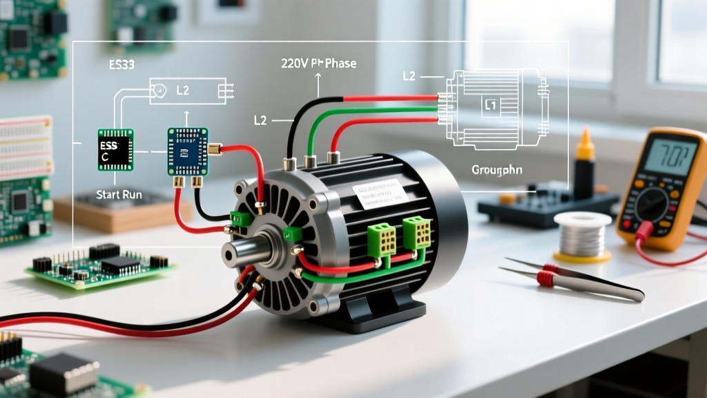
Most dual-voltage single-phase induction motors (115V/230V) utilize an 8-terminal configuration labeled T1 through T8. The fundamental principle of dual-voltage wiring is how the two internal run windings are configured. For high voltage (220V/230V), the run windings are wired in series. For low voltage (110V/115V), they are wired in parallel. The start winding and centrifugal switch circuit remain in parallel with one of the run windings in both configurations.
Standard 8-Terminal High Voltage (220V/230V) Mapping
Below is the standard NEMA terminal connection matrix for wiring a single-phase motor to a 220V/230V supply. Always confirm this matches the diagram printed on the inside of your motor's connection box cover.
| Connection Point | Terminals to Splice/Jump | Wire Nut / Lug Action |
|---|---|---|
| Run Winding Series Link | T2, T3, and T8 | Splice together and insulate |
| Start Winding Link | T5 and T7 | Splice together and insulate |
| Line 1 (Hot / Black) | T1 | Connect to L1 Supply |
| Line 2 (Hot / Red) | T4 | Connect to L2 Supply |
Reversing the Motor Rotation Direction
Single-phase motors do not have a 'phase rotation' like 3-phase motors. To reverse the direction of a capacitor-start induction motor, you must reverse the polarity of the start winding relative to the run winding. On a standard T1-T8 terminal block, this is achieved by swapping the positions of T5 and T8.
Step-by-Step Reversal:
- Disconnect all power and verify zero energy state with a CAT III multimeter.
- Remove the splice connecting T2, T3, and T8.
- Remove the splice connecting T5 and T7.
- Create a new splice connecting T2, T3, and T5.
- Create a new splice connecting T8 and T7.
- Leave L1 on T1 and L2 on T4.
Sizing Conductors and Overcurrent Protection (NEC Article 430)
Wiring a 220V motor is not as simple as matching the FLA to a standard branch circuit breaker. NEC Article 430 dictates specific multipliers for conductor sizing and overcurrent protection to accommodate the massive inrush current (Locked Rotor Amps) that occurs during startup, which can be 6 to 8 times the FLA.
Motor Circuit Sizing Matrix (230V Single-Phase)
| Motor HP | Nameplate FLA (Approx) | Min Wire Ampacity (FLA x 1.25) | Recommended THHN Copper Wire | Max Inverse Time Breaker (FLA x 2.50) |
|---|---|---|---|---|
| 2 HP | 12.0 A | 15.0 A | 14 AWG (12 AWG preferred) | 30 A |
| 3 HP | 17.0 A | 21.25 A | 10 AWG | 40 A |
| 5 HP | 28.0 A | 35.0 A | 8 AWG | 70 A |
As noted in OSHA 1910.305 Wiring Methods, flexible cords are generally prohibited for fixed motor wiring; you must use THHN/THWN in conduit or XHHW cable. Furthermore, while a 3HP motor draws only 17A, the NEC allows a 40A breaker to prevent nuisance tripping during startup. The actual running overload protection is handled by the thermal overloads inside the motor starter or the motor's internal thermal protector, not the branch circuit breaker.
The Role of Start Capacitors and the Centrifugal Switch
Single-phase 220V motors require a phase shift to generate starting torque. This is achieved via a start capacitor (e.g., a Dayton 2MDV8, typically 300-400 MFD, costing around $18-$25 in 2026) and a centrifugal switch. When you apply 220V, current flows through the start winding and the capacitor. Once the motor reaches roughly 75% of its synchronous speed (e.g., 2550 RPM for a 4-pole motor), the centrifugal switch mechanically opens, dropping the start capacitor out of the circuit. The motor then runs solely on the main run windings.
If you are wiring a Capacitor-Start/Capacitor-Run (CSCR) motor, the diagram will include an additional run capacitor (usually 10-50 MFD, 370VAC) that remains in the circuit continuously via a potential relay or specific terminal taps, improving running efficiency and power factor.
Troubleshooting Common 220V Motor Failures
Even with a perfect 220v electric motor wiring diagram execution, mechanical and electrical failures occur. According to Department of Energy motor efficiency guidelines, proper troubleshooting extends motor life and prevents secondary damage to driven equipment.
- Motor Hums but Will Not Start: The run windings are energized, but the start circuit is failing. This is almost always a blown start capacitor, a welded-shut centrifugal switch, or an open circuit in the start winding (T5-T8 path). Test the capacitor with a multimeter's capacitance setting; it should read within ±20% of its MFD rating.
- Breaker Trips Instantly Upon Energization: This indicates a dead short. Either the motor windings have shorted to the frame (ground fault), the run windings have shorted together, or the start capacitor has failed in a shorted state. Disconnect the motor from the load to rule out a locked-rotor condition on the driven equipment (e.g., a seized compressor pump).
- Motor Starts but Runs Hot and Draws High Amps: Check for low supply voltage. A 230V motor operating at 205V due to excessive voltage drop over a long wire run will draw proportionally higher amperage to maintain its wattage output, leading to rapid insulation breakdown. Always measure voltage at the motor terminals under load.
Grounding and Equipment Safety
No 220v electric motor wiring diagram is complete without the Equipment Grounding Conductor (EGC). The metal frame of the motor must be bonded to the system ground. Per NEC 250.122, the EGC must be sized based on the rating of the overcurrent device, not the FLA. For a 3HP motor on a 40A breaker, you must run a minimum of a 10 AWG copper ground wire alongside your current-carrying conductors, terminating it to the motor's dedicated green grounding screw or the grounded junction box housing. For a comprehensive look at standardizing motor dimensions and terminal markings, refer to the NEMA MG-1 Motors and Generators Standard.
By strictly adhering to the terminal mapping, respecting NEC sizing multipliers, and understanding the mechanical nuances of the starting circuit, you ensure your 220V single-phase motor delivers reliable, high-torque performance for years to come.