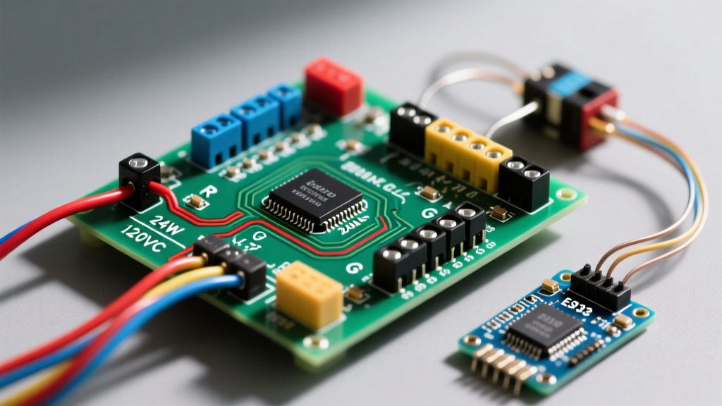

Decoding the Standard Furnace Control Board Terminals
When you remove the blower compartment door of a modern gas furnace, the control board is the central nervous system governing the entire heating sequence. Whether you are looking at a Honeywell ST9120U, a White-Rodgers 50E47, or an OEM Carrier ICP board, understanding the wiring diagram for a furnace is critical for both installation and diagnostics. As of 2026, with the widespread adoption of high-efficiency condensing furnaces and ECM (Electronically Commutated Motor) blowers, these diagrams have become more complex, integrating digital communication lines alongside traditional analog voltage pathways.
Before touching any wire, always engage the lockout/tagout (LOTO) procedure on the 120VAC service disconnect. The control board handles both lethal line voltage (120VAC) and low-voltage control circuits (24VAC). Below is a breakdown of the standard terminal designations you will find on the schematic pasted inside the furnace panel.
| Terminal Label | Voltage Type | Primary Function |
|---|---|---|
| R / Rc / Rh | 24VAC Hot | Provides 24VAC power from the transformer to the thermostat. |
| W / W1 | 24VAC Return | First-stage heat call. Closes the circuit to initiate the heating sequence. |
| Y / Y1 | 24VAC Return | First-stage cooling call. Engages the outdoor condenser contactor. |
| G | 24VAC Return | Fan-only call. Energizes the blower motor relay independently of heat/cool. |
| C | 24VAC Common | The common return path for the 24VAC transformer secondary. |
| EAC / HUM | 120VAC / 24VAC | Electronic Air Cleaner / Humidifier. Energizes only during a blower run cycle. |
| L1 / L2 | 120VAC Line | Main line voltage input from the service disconnect switch. |
Step-by-Step Trace: Reading the Diagram for a Gas Furnace
A schematic is not just a map of connections; it is a chronological story of the furnace's sequence of operation. When a homeowner turns up the thermostat, the board follows a strict, safety-interlocked timeline. Here is how to trace that sequence on the wiring diagram.
1. The Call for Heat (24VAC Circuit)
The sequence begins at the thermostat. When the room temperature drops below the setpoint, the thermostat closes the internal relay between the R and W terminals. On the furnace control board, you will measure 24VAC between the R and C terminals, and 0VAC between W and C (because the closed thermostat switch drops the voltage to near zero, completing the circuit). The microprocessor registers this voltage drop and initiates the pre-purge phase.
2. Inducer Motor and Pressure Switch (120VAC & 24VAC)
The board energizes the draft inducer motor via a 120VAC relay. The wiring diagram will show the inducer motor wired in series with the high-limit switch and the primary control board's internal relay. As the inducer creates a negative pressure in the heat exchanger, it pulls the diaphragm on the pressure switch closed. The diagram illustrates this pressure switch wired between the 24VAC hot (usually a dedicated 'PS' terminal or routed through the R circuit) and the microprocessor input pin. If the pressure switch fails to close within 15 to 30 seconds, the board aborts the cycle and flashes a 3-blink error code.
3. Ignition Sequence (120VAC)
Once the pressure switch proves draft, the board sends 120VAC to the Hot Surface Igniter (HSI). According to the U.S. Department of Energy, modern silicon carbide or silicon nitride igniters draw between 3 to 5 amps during the warm-up phase. The wiring diagram will route this through a dedicated IGN relay. After 4 to 9 seconds of warm-up, the board opens the gas valve circuit.
4. Gas Valve and Blower Engagement
The gas valve requires 24VAC to open its main solenoid. The diagram shows the gas valve wired between the board's 'GV' terminal and the 24VAC Common (C). Once the flame sensor detects microamp current (typically 2.0 to 5.0 µA) confirming combustion, the board waits an additional 30 to 45 seconds before energizing the main blower motor. In 2026 models featuring ECM motors, the diagram will not show standard 120VAC taps for heating and cooling speeds; instead, it will show a multi-pin communication harness (like a 5-pin Molex connector) sending digital PWM signals from the board to the motor module.
Pro Diagnostic Tip: Always check the 3-amp ATO automotive fuse located on the control board before assuming the microprocessor is dead. This fuse protects the 24VAC transformer. If a thermostat wire shorts to ground (common when installers strip the 'G' or 'Y' wire too far and it touches the metal chassis), this fuse will blow instantly to save the $150-$450 control board.
Common Wiring Failures and Multimeter Diagnostics
Even with a perfect understanding of the wiring diagram for a furnace, field conditions introduce variables. Here are three specific failure modes and how to diagnose them using a digital multimeter (such as a Fluke 117 set to V AC or Ohms).
- Open High-Limit Switch: The limit switch is a normally-closed (NC) safety device wired in series with the 120VAC gas valve or inducer circuit. If the blower fails or the air filter is severely clogged, the heat exchanger overheats, and the bi-metallic disc opens the circuit. Diagnostic: Set your multimeter to continuity (Ohms). With power off, place probes across the limit switch terminals. An 'OL' (Open Line) reading confirms a tripped or failed switch.
- Flame Sensor Grounding Issue: The flame sensor relies on flame rectification, which requires a solid DC microamp signal returning to the board through the ground plane. If the furnace is not properly grounded, or if the sensor is coated in silica from newly installed drywall dust, the board will not detect the flame and will shut off the gas valve after 3 seconds. Diagnostic: Measure the voltage between the neutral bar in the main panel and the furnace chassis; it should be less than 1V AC. Clean the sensor with fine steel wool, never sandpaper.
- Transformer Failure: If you have 120VAC entering the board at L1 and L2, but 0VAC at the R and C terminals, the 40VA step-down transformer has likely failed. Diagnostic: Check the primary side (120VAC) and secondary side (24VAC) with the power on. If primary voltage is present but secondary is zero, replace the transformer.
Upgrading to a Smart Thermostat: The C-Wire Dilemma
One of the most common reasons DIYers consult a furnace wiring diagram today is to install a smart thermostat like a Nest, Ecobee, or Honeywell T9. These devices require continuous 24VAC power to run their Wi-Fi radios and displays, which necessitates a dedicated Common (C) wire.
Older furnace diagrams often do not route a C-wire to the thermostat bundle. If you connect the C terminal on the board to the thermostat, you must ensure you are not disrupting the existing AC contactor circuit. If running a new 18/5 thermostat cable is impossible, technicians often use an 'Add-A-Wire' kit or repurpose the unused HUM or EAC terminals. However, the wiring diagram will show that HUM/EAC terminals only output 120VAC (or 24VAC on specific boards) when the blower is running. If you wire a smart thermostat's C-wire to a blower-dependent terminal, the thermostat will lose power and reboot every time the heating cycle ends, eventually corrupting its internal memory. Always trace the schematic to verify if a terminal provides continuous 24VAC or switched voltage.
Safety Protocols and NEC Compliance
When modifying or repairing furnace wiring, adherence to the NFPA 70 National Electrical Code (NEC) is non-negotiable. Article 430 covers motor circuits, dictating the proper wire gauge and overcurrent protection for the blower and inducer motors. Furthermore, Article 440 specifically addresses air-conditioning and refrigerating equipment, outlining the requirements for the external service disconnect.
The NEC requires that a dedicated 120VAC, 15-amp or 20-amp circuit supplies the furnace, and an accessible disconnect switch must be located within sight of the appliance. In modern installations, following ENERGY STAR HVAC guidelines also means ensuring that the control board's grounding lug is securely fastened to a clean, unpainted metal surface on the chassis to prevent electromagnetic interference (EMI) from disrupting the microprocessor's flame-sensing algorithms.
Frequently Asked Questions
Why does my furnace wiring diagram show two different 'W' terminals?
Many modern two-stage furnaces feature W1 and W2 terminals. W1 controls the first-stage (low-fire) gas valve solenoid, while W2 controls the second-stage (high-fire) solenoid. The wiring diagram will illustrate how the board modulates between these based on outdoor temperature sensors or thermostat algorithms to maintain a steady AFUE (Annual Fuel Utilization Efficiency) rating.
Can I bypass a safety switch shown on the diagram to test the furnace?
You can temporarily bypass a pressure switch or limit switch strictly for diagnostic purposes using a jumper wire to prove continuity, but you must never leave a bypass in place. Doing so removes critical fail-safes and can lead to catastrophic heat exchanger failure or carbon monoxide leakage. Always replace faulty safety devices with OEM-specified components.