
The High Cost of Skipping the Planning Phase
Installing a trailer harness is no longer just about splicing a few copper wires together. In modern 2024–2026 vehicles, the lighting circuits are heavily integrated into the vehicle's Controller Area Network (CAN-bus) and managed by a highly sensitive Body Control Module (BCM). A single misread tow hitch electrical wiring diagram or an overloaded circuit can send a 12V backfeed directly into the BCM, resulting in a catastrophic failure that costs between $1,200 and $2,500 to diagnose and replace.
This installation planning guide is designed for DIYers and fleet technicians who want to get the job done right the first time. Before you grab a pair of wire strippers or crawl under the rear bumper, you must map out your connector type, calculate voltage drop over the trailer's length, and select the appropriate integration module. According to FMCSA Regulation 393.9, all commercial and heavy-duty towing setups must meet strict luminosity and redundancy standards, making proper wire gauge selection a legal necessity, not just a best practice.
Identifying Your Connector Architecture
The first step in planning is matching the vehicle-side harness to the trailer-side receptacle. While adapters exist, relying on them for heavy-duty towing introduces resistance points that generate heat and cause voltage drop. Below is the definitive matrix for North American standard connectors.
| Connector Type | Primary Use Case | Pin Count | Key Added Feature vs. 4-Way |
|---|---|---|---|
| 4-Way Flat | Light-duty utility, small boat trailers | 4 | Baseline (Tail, Left Turn, Right Turn, Ground) |
| 5-Way Flat | Marine trailers with surge brakes | 5 | Reverse light circuit to lock out surge brakes |
| 6-Way Round | Horse trailers, heavy equipment | 6 | 12V auxiliary power and electric brake controller |
| 7-Way RV Blade | Modern RVs, campers, heavy car haulers | 7 | Standardized SAE J286 layout, dedicated reverse and aux |
Pro Tip: If you are wiring a 7-way RV blade, ensure you are following the SAE J286 standard pinout. Many older aftermarket diagrams swap the 12V auxiliary and electric brake pins, which will instantly fry your brake controller upon connection.
Decoding the Tow Hitch Electrical Wiring Diagram
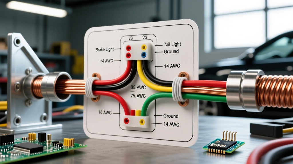
When reviewing your specific tow hitch electrical wiring diagram, pay strict attention to the wire color codes. While the trailer side usually adheres to a strict standard (White = Ground, Brown = Tail/Running, Yellow = Left, Green = Right), the vehicle side is notoriously inconsistent. Automakers frequently use proprietary color schemes. For instance, a 2025 Ford F-150 might use a Violet/White stripe for the left turn signal, while a Toyota Tacoma might use a solid Green wire for the exact same function.
Expert Insight: Never trust wire colors blindly on the vehicle side of the B-pillar. Always use a digital multimeter or a logic probe to verify the circuit's function at the exact point where you plan to tap into the harness. For verified OEM pinouts, consult Curt Manufacturing's wiring support database or the vehicle's specific service manual.
Wire Gauge Selection & Voltage Drop Calculations
The most common failure mode in DIY trailer wiring is using the cheap, 18 AWG wire included in budget $20 Amazon kits. When you run 20 feet of 18 AWG wire to power a set of traditional incandescent trailer lights pulling 8 amps, you will experience a severe voltage drop, resulting in dim lights and hyper-flashing turn signals.
For modern installations, especially those utilizing electric brakes or auxiliary charging lines, you must upsize your wiring. Use the following matrix to plan your wire purchases:
| Circuit Function | Max Amperage | Minimum Wire Gauge (Under 20ft) | Recommended Wire Gauge (20ft+) |
|---|---|---|---|
| Ground (White) | Varies | 12 AWG | 10 AWG |
| Tail / Running Lights (Brown) | 5A - 10A | 16 AWG | 14 AWG |
| Turn Signals (Yellow/Green) | 5A - 10A | 16 AWG | 14 AWG |
| Electric Brakes (Blue) | 15A - 20A | 12 AWG | 10 AWG |
| 12V Aux / Charging (Black/Red) | 20A - 40A | 10 AWG | 8 AWG |
Note: If you are upgrading to all-LED trailer lighting, the amperage draw drops significantly (often under 2A total). However, you must still use at least 16 AWG wire for physical durability and resistance to road debris impacts.
Modern Vehicle Integration: T-Connectors vs. ZCI Modules
How you extract the signal from the vehicle is the most critical decision in your planning phase. You generally have two choices:
1. Plug-and-Play T-Connectors
If your vehicle came with a factory tow package (or even just a pre-wired rear harness), a T-connector like the Tekonsha 118467 or Curt 56367 is the ideal choice. These cost between $40 and $80 and plug directly inline between the vehicle's tail light and the factory harness. They include a built-in modulite that draws power directly from the battery via a separate 12V feed wire, protecting the vehicle's delicate lighting circuits from the trailer's amperage draw.
2. Zero Contact Interface (ZCI) Modules
For vehicles with multiplexed wiring, PWM (Pulse Width Modulation) lighting, or delicate CAN-bus systems (common in European imports and newer domestic SUVs), standard hardwiring is a massive risk. A ZCI module, such as the Tekonsha 119250 (approx. $130), uses magnetic induction sensors that clamp around the outside of the vehicle's wires. It reads the magnetic field generated by the current flow without ever piercing the wire insulation or making physical contact with the copper. This guarantees zero backfeed into the vehicle's computer.
Routing, Grounding, and Environmental Sealing
A perfect wiring diagram is useless if the physical installation fails due to environmental exposure. Plan your routing to avoid exhaust components (which can melt wire looms) and suspension travel zones (which can shear wires). Always use split-loom tubing and secure it with UV-resistant zip ties every 12 inches.
The absolute most critical step is the ground. The white ground wire must be bonded to a clean, bare metal surface on the vehicle's chassis. Use a sanding disc to remove paint and clear coat down to bare steel. Secure it with a stainless steel bolt and a flange nut—never rely on self-tapping screws into thin sheet metal, as vibration will loosen them over time. Finally, coat the connection in a heavy layer of dielectric grease (like Permatex 22058) to prevent galvanic corrosion.
Pre-Flight Checklist Before Powering Up
Before you connect the trailer or apply 12V power to the battery feed wire, run through this final verification checklist:
- Continuity Check: Use a multimeter to verify there are no short circuits between the ground wire and any of the power circuits.
- Module Mounting: Ensure the converter box is mounted vertically with the wire exits pointing downward to prevent water pooling inside the case.
- Fuse Verification: Confirm the inline fuse on the 12V battery feed wire is properly rated (usually 10A for lighting-only, 20A-30A for auxiliary circuits) and located within 18 inches of the battery terminal.
- Signal Test: Use a dedicated trailer circuit tester (like the PTW2993) to verify each pin on the vehicle-side plug before plugging in the actual trailer.
By thoroughly planning your installation using a verified tow hitch electrical wiring diagram and respecting modern automotive electrical architectures, you ensure a safe, reliable, and legally compliant towing setup for years to come. For further troubleshooting and vehicle-specific guides, reference eTrailer's comprehensive wiring database.