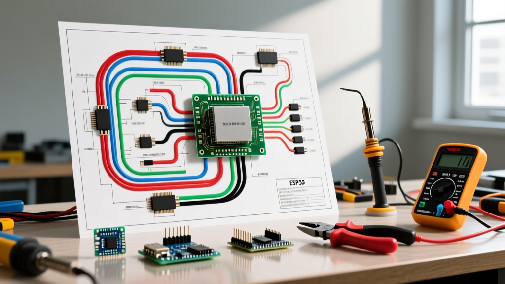

The Evolution of Automotive Electrical Wiring Diagrams
If you are still looking for a simple switch-and-bulb loop, you are working on a vehicle from the 1980s. In modern 2026 vehicle architectures, reading automotive electrical wiring diagrams requires an understanding of multiplexed networks, Body Control Modules (BCMs), and Pulse Width Modulation (PWM). A headlight circuit is no longer just a relay and a wire; it is a logic-driven system monitored for current draw, short circuits, and CAN bus communication.
This step-by-step walkthrough will guide you through tracing a modern BCM-controlled headlight and Daytime Running Light (DRL) circuit. We will cover schematic decoding, tool selection, and precise diagnostic measurements to help you isolate faults without throwing unnecessary parts at the vehicle.
Phase 1: Decoding the Schematic Standards
Before picking up a multimeter, you must understand the language of the diagram. Most global manufacturers adhere to SAE International standards for wire sizing and DIN 72552 for terminal numbering. Recognizing these terminal designations on a wiring diagram saves hours of diagnostic time.
Critical DIN Terminal Numbers
- Terminal 30: Direct battery positive (hot at all times).
- Terminal 15: Ignition-switched positive (hot in Run/Start).
- Terminal 31: Direct battery negative (chassis ground).
- Terminal 50: Starter control circuit.
- Terminal 87 / 87a: Relay outputs (Normally Open / Normally Closed).
Pro Tip: When tracing automotive electrical wiring diagrams for European vehicles (BMW, VW, Volvo), you will frequently see 'X' designation for load-shedding circuits. Terminal 'X' is powered only when the ignition is ON, but drops out during engine cranking to preserve battery voltage for the starter and ECU.
Phase 2: Tool Selection & Calibration
Modern modules will set Diagnostic Trouble Codes (DTCs) if they detect abnormal resistance or voltage spikes caused by improper testing tools. Throw away your wire-piercing probes; they compromise wire insulation and invite corrosion, leading to intermittent faults months down the road.
The 2026 Diagnostic Toolkit
| Tool | Model Recommendation | Approx. Cost | Primary Use Case |
|---|---|---|---|
| Digital Multimeter (DMM) | Fluke 87V or 88V | $450 - $550 | Voltage drop testing, resistance, continuity |
| Circuit Tester | Power Probe IV | $250 - $300 | Applying power/ground, checking diode drops |
| Oscilloscope | PicoScope 4425A | $1,200 - $1,400 | Viewing PWM duty cycles, CAN bus waveforms |
| Back-Pin Probes | Assorted T-Pin / U-Probes | $25 - $40 | Safe connector cavity testing without damage |
Phase 3: Step-by-Step Walkthrough (BCM Headlight Circuit)
Let us trace a fault where the driver-side low beam is inoperative, but the DRL functions correctly. The NHTSA Federal Motor Vehicle Safety Standards (FMVSS 108) dictate strict output requirements for these circuits, meaning the BCM actively monitors the current draw to ensure compliance and bulb health.
Step 1: Verify the Power Feed (Terminal 30)
Locate the BCM power feed on the wiring diagram. It will typically originate from the Battery Junction Box (BJB) via a high-amperage fuse (e.g., Fuse F12, 40A).
- Set your Fluke 87V to DC Volts.
- Back-probe the BCM connector cavity designated for Terminal 30 power.
- Measure against a known good engine block ground.
- Expected Result: 12.4V to 12.6V (engine off). If you read 11.8V or lower, you have high resistance in the power feed. Perform a voltage drop test across the fuse and wiring before condemning the BCM.
Step 2: Trace the Switch Input Logic
The headlight switch on the steering column does not carry headlight current. It sends a 5V or 12V reference signal to the BCM. When you turn the switch to 'ON', the internal resistor network drops this voltage to near 0V, signaling the BCM to activate the output.
- Locate the Headlamp Switch Input wire on the diagram (e.g., Circuit 150, Wire Color: VT/YE - Violet with Yellow stripe).
- Back-probe the switch connector.
- With the switch OFF, you should read 5.0V or 12.0V (depending on OEM architecture).
- Turn the switch ON. The voltage must drop to less than 0.1V.
- Failure Mode: If the voltage only drops to 1.5V, the BCM will not recognize the 'ON' command due to a corroded switch contact or a chafed wire creating a parallel resistance path.
Step 3: Analyze the Output and PWM Signal
This is where modern automotive electrical wiring diagrams differ from legacy systems. The BCM output to the headlamp is often a PWM (Pulse Width Modulation) signal, especially for LED DRLs and adaptive lighting.
- Connect your PicoScope or advanced DMM to the BCM output wire (e.g., Circuit 152, Wire Color: WH/BU - White with Blue stripe).
- Turn on the low beams. A standard DMM might show a fluctuating or averaged voltage (e.g., 8.5V), which is misleading.
- Switch to the oscilloscope. You should see a square wave toggling between 0V and 13.5V.
- Diagnostic Insight: For full low-beam intensity, the duty cycle should be 95-100%. If the DRL is active, the BCM drops the duty cycle to 20-30% to dim the LED array. If your scope shows a flat 0V despite a good input signal and good ground, the BCM internal MOSFET driver has failed.
Step 4: Validate the Ground Path (Terminal 31)
A headlight circuit is only as good as its ground. Ground points (e.g., G101, located in the left front wheel well) are notorious for corrosion.
- Leave the headlight ON (or command it ON via a bi-directional scan tool).
- Set your DMM to DC Volts.
- Place the red probe on the headlamp ground pin and the black probe directly on the negative battery terminal.
- Acceptable Threshold: Less than 0.1V drop. If you read 0.4V or higher, the ground is compromised. Clean the G101 ring terminal and chassis mating surface with a wire brush and apply dielectric grease.
SAE J1128 Wire Gauge & Ampacity Matrix
When repairing or modifying circuits based on automotive electrical wiring diagrams, you must match the wire gauge to the OEM specification. Using undersized wire causes voltage drop and potential fire hazards. The following matrix is based on standard SAE J1128 low-tension primary cable ratings for a 12V system in a standard engine bay environment (up to 105°C).
| AWG Size | Metric (mm²) | Max Continuous Amps | Typical Application |
|---|---|---|---|
| 20 AWG | 0.50 mm² | 4A - 5A | CAN bus lines, sensor signals, switch inputs |
| 18 AWG | 0.80 mm² | 6A - 8A | Interior LED lighting, module wake-up circuits |
| 16 AWG | 1.00 mm² | 10A - 12A | Fuel injectors, blower motor relays |
| 14 AWG | 2.00 mm² | 15A - 18A | Headlight power feeds, power windows |
| 12 AWG | 3.00 mm² | 20A - 25A | Seat heaters, high-amperage accessory feeds |
| 10 AWG | 5.00 mm² | 30A - 40A | Main BCM power feeds, ABS module power |
Advanced Edge Cases: CAN Bus Interference & Parasitic Draws
When tracing automotive electrical wiring diagrams, you must account for the vehicle's network topology. A common edge case occurs when an aftermarket accessory (like an LED headlight conversion kit) lacks proper CAN bus decoders. Because LEDs draw significantly less current than halogen bulbs, the BCM interprets the low current draw as a 'bulb out' condition. It will then rapidly pulse the circuit (hyper-flashing) or shut it down entirely to protect the wiring.
The Backfeed Phenomenon
If a ground wire (Terminal 31) for a specific module fails, the module will attempt to find a path to ground through alternative routes. This often results in current backfeeding through the CAN High or CAN Low communication lines. ASE Certification guidelines heavily emphasize testing network integrity when seemingly unrelated modules begin throwing communication DTCs (U-codes). If your headlight repair suddenly triggers a U0140 (Lost Communication with BCM) code, check your ground circuits before replacing the module.
Final Diagnostic Verification
Once the fault is isolated and repaired, clear all DTCs and perform a BCM sleep-cycle test. Modern vehicles can take up to 20 minutes to enter 'sleep mode' after the ignition is turned off and the doors are locked. Use a clamp-on DC amp meter (like the Fluke i410) around the negative battery cable. The parasitic draw must drop below 30mA. If the draw remains at 200mA+, your repair has inadvertently kept a module awake on the network, which will lead to a dead battery by morning.
Mastering automotive electrical wiring diagrams is not about memorizing every circuit; it is about understanding the logic flow, respecting the terminal standards, and using precision tools to validate the physics of the circuit. Stick to the step-by-step methodology, and you will diagnose complex electrical faults with absolute confidence.