
The Critical Intersection of Garage Door Openers and Electrical Code
When planning the electrical layout for a residential garage, the garage door opener is often treated as an afterthought. However, the harsh environmental conditions of a garage—combined with the heavy inductive loads of motorized lift systems—make this one of the most strictly regulated circuits in modern residential electrical work. Understanding the correct wiring diagram for garage door opener systems is not just about ensuring the device powers on; it is about adhering to stringent life-safety codes, preventing electrical fires, and ensuring the safety reversal systems operate without interruption.
In 2026, electrical inspectors are strictly enforcing recent updates to the National Electrical Code (NEC) regarding Ground Fault Circuit Interrupter (GFCI) protection and dedicated branch circuits in garages. This guide provides a comprehensive, code-compliant wiring blueprint, breaking down both the 120V line-voltage supply and the low-voltage safety sensor circuits.
Decoding the NEC: GFCI and Dedicated Circuit Mandates
Before pulling a single foot of wire, you must understand the two foundational NEC articles that govern garage door opener receptacles. Ignoring these will result in an immediate inspection failure and potential safety hazards.
1. The GFCI Requirement (NEC Article 210.8(A)(2))
Historically, there was an exception in the NEC that allowed ceiling-mounted receptacles dedicated solely to garage door openers to bypass GFCI protection if they were not 'readily accessible.' This exception was completely deleted in the 2020 NEC and remains absent in the 2023/2026 codes. Today, every 125-volt, single-phase, 15- and 20-ampere receptacle installed in a garage must have GFCI protection. This includes the ceiling receptacle powering your opener. To prevent nuisance tripping from motor arcing, modern manufacturers like Chamberlain and LiftMaster have integrated advanced EMI (Electromagnetic Interference) filters into their 2024-2026 models, such as the Chamberlain B970T and LiftMaster 8500W.
2. The Dedicated Branch Circuit (NEC Article 210.11(C)(4))
The NEC mandates that at least one 120-volt, 20-ampere branch circuit must be installed to supply garage receptacle outlets, and this circuit shall have no other outlets. This means your garage door opener cannot share a circuit with garage lighting, a deep freezer, or workbench power tools. It requires a dedicated 20A line to handle the initial inrush current (LRA - Locked Rotor Amps) of the motor without causing voltage drops that could disrupt the logic board or safety sensors.
Line-Voltage Wiring Diagram: Panel to Receptacle
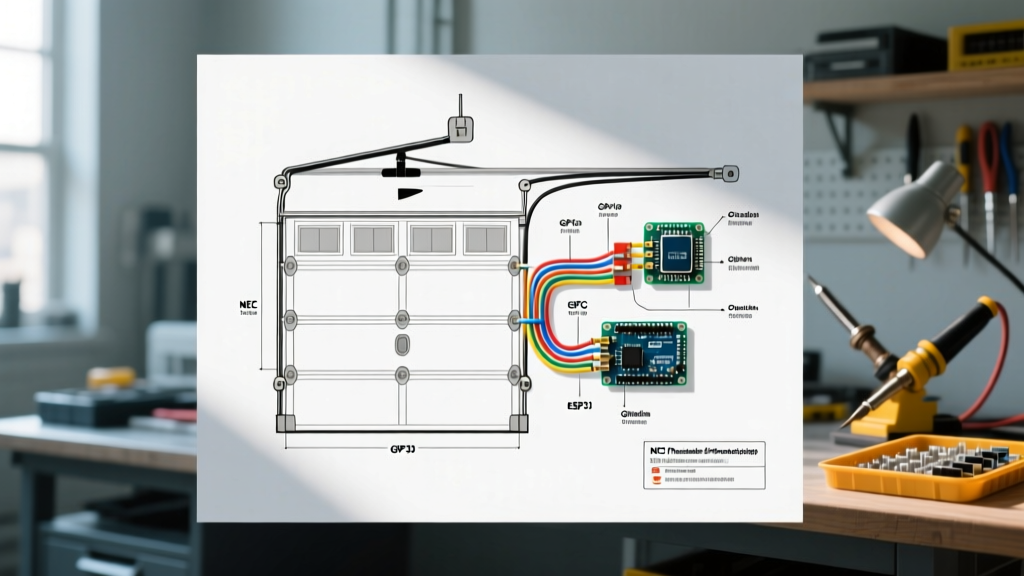
The primary wiring diagram for a standard trolley-style garage door opener follows a direct, dedicated path from the main service panel to the ceiling-mounted receptacle.
- Main Panel: Install a 20-Amp Dual-Function (AFCI/GFCI) breaker (e.g., Siemens Q120DF or Eaton BR220GF). AFCI (Arc Fault) protection is required by NEC 210.12 for all 120V branch circuits supplying garages.
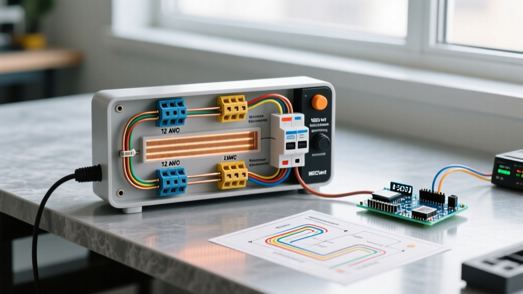
- Wire Routing: Run 12/2 NM-B (Romex) cable from the panel to the ceiling junction box. While 14 AWG is technically rated for 15A, a 20A circuit using 12 AWG is the industry standard for garages to accommodate voltage drop over longer runs and future-proof the circuit.
- Ceiling Receptacle: Terminate the 12/2 NM-B into a 20A, 125V single duplex receptacle. Ensure the grounding pigtail is securely bonded to the metal junction box if applicable.
- Opener Connection: Plug the opener's factory-installed power cord directly into the receptacle. NEC Article 400.8 strictly prohibits using extension cords as a substitute for fixed wiring. If the factory cord does not reach, the receptacle must be relocated, or a licensed electrician must hardwire a longer, UL-listed power supply cord to the unit.
Component Specification Matrix
| Component | Specification / Rating | NEC Code Reference |
|---|---|---|
| Circuit Breaker | 20A Dual-Function (AFCI/GFCI) | 210.8(A)(2) & 210.12(A) |
| Branch Circuit Wiring | 12/2 NM-B with Ground (Copper) | 334.10 & 240.4(D) |
| Receptacle | 20A, 125V, Single Duplex, Tamper-Resistant | 406.12 & 210.52(G) |
| Maximum Continuous Load | ~5 to 7 Amps (Standard 3/4 HP to 1.25 HP DC Motors) | 210.20(A) |
Jackshaft vs. Trolley Opener: Receptacle Placement
The physical wiring diagram changes significantly depending on the type of opener you install. Standard trolley openers (which hang from the ceiling rail) require a ceiling-mounted receptacle directly above the motor head. However, Jackshaft openers (like the LiftMaster 8500W) mount on the wall beside the torsion spring shaft.
For jackshaft models, the receptacle must be installed on the wall, within 3 feet of the motor head, and at least 6 feet above the floor to remain out of the way of vehicles and storage, while still complying with accessibility rules. Routing 12/2 NM-B down a finished drywall wall requires proper nail-plate protection (NEC 300.4) wherever the cable passes through wooden studs within 1.25 inches of the stud edge.
Low-Voltage Control & Safety Reversal Wiring (UL 325)
The 120V power supply is only half the diagram. The low-voltage wiring controls the logic board, wall buttons, and critical safety sensors. According to the U.S. Consumer Product Safety Commission (CPSC) and the UL 325 standard, all residential garage door openers manufactured after 1993 must feature photoelectric eye sensors that reverse the door if an object breaks the beam.
Sensor Wiring Specifications
- Wire Type: 2-conductor, 22 AWG stranded bell wire. Do not run this low-voltage wire in the same conduit or staple it directly alongside the 120V NM-B cable to prevent inductive interference, which can cause sensor flickering.
- Sensor Height: The UL 325 standard strictly mandates that photoelectric sensors must be mounted no higher than 6 inches above the garage floor. Mounting them higher to avoid dirt or snow is a severe code violation and creates a crush hazard for small children or pets.
- Alignment: The sending sensor (usually with a yellow LED) and receiving sensor (green LED) must have an unobstructed line of sight. The logic board operates on a 6 VDC pulsed signal; even a slight misalignment will drop the voltage below the threshold, preventing the door from closing.
Common Code Violations & Troubleshooting Edge Cases
Even with a perfect wiring diagram on paper, field conditions often introduce edge cases. Here is how to troubleshoot the most common compliance and operational failures:
Expert Insight: If your newly installed AFCI/GFCI breaker trips immediately when the garage door opener motor engages, do not simply swap it for a standard breaker. Older openers with brushed DC or AC motors generate massive carbon arcing and harmonic noise. Upgrading the opener to a modern model with a brushless DC motor and integrated EMI filtering (like the 2025+ Chamberlain secure-view models) will resolve the nuisance tripping while maintaining code compliance.
Troubleshooting Matrix: GFCI Nuisance Tripping
| Symptom | Probable Cause | Code-Compliant Solution |
|---|---|---|
| Breaker trips instantly upon motor start. | High inrush current or severe EMI from worn motor brushes. | Replace opener with brushless DC model; verify 20A breaker rating. |
| Breaker trips randomly during rainstorms. | Moisture ingress in exterior wall junction boxes or conduit. | Seal conduit fittings; apply dielectric grease to exterior connections. |
| Opener loses memory/settings after tripping. | Lack of battery backup on a GFCI-protected circuit. | Install an opener with an integrated 12V DC battery backup (e.g., LiftMaster 8550WLB). |
Step-by-Step Installation Safety Protocol
Adhering to the wiring diagram is futile if the physical installation compromises safety. Follow this strict protocol:
- Lockout/Tagout (LOTO): Shut off the main 20A breaker and apply a physical lock. Verify zero voltage at the ceiling junction box using a CAT III multimeter before stripping any wires.
- Torque Specifications: When terminating the 12 AWG wires to the receptacle, use a torque screwdriver set to the manufacturer's specification (typically 14-16 in-lbs for standard 20A receptacles) to prevent loose connections that cause arc faults.
- Sensor Validation: After wiring the 22 AWG bell wire, test the safety reversal system. Place a 1.5-inch block of wood (or a 2x4 laid flat) on the floor under the door. Close the door. Upon contacting the wood, the door must automatically reverse within 2 seconds. This is a mandatory test outlined by the Door and Access Systems Manufacturers Association (DASMA).
- Manual Release Check: Ensure the emergency release cord hangs no lower than 6 feet from the floor to prevent entanglement hazards, while remaining accessible to an average-height adult.
Final Thoughts on Garage Electrical Safety
Designing and executing a safe wiring diagram for a garage door opener requires balancing heavy-duty power delivery with sensitive low-voltage logic. By strictly adhering to NEC Articles 210.8, 210.11, and the UL 325 safety standards, you ensure that the system operates reliably for years without posing fire or crush risks. Always consult the latest edition of the National Electrical Code (NFPA 70) and your local municipality's amendments before beginning any electrical work, as local inspectors may have stricter requirements regarding AFCI protection zones and receptacle heights.