
The Critical Role of SAE J286 and DOT Compliance in Trailer Braking
When towing heavy loads, the margin between a safe stop and a catastrophic jackknife event is measured in milliseconds and millivolts. Electric trailer brakes are not merely an accessory; they are a heavily regulated safety system. According to the National Highway Traffic Safety Administration (NHTSA), improper trailer wiring and inadequate brake gain are leading contributors to multi-vehicle highway collisions. As of 2026, Department of Transportation (DOT) enforcement and commercial inspection standards have become increasingly stringent regarding trailer electrical compliance.
Designing and executing a proper wiring diagram for electric trailer brakes requires strict adherence to the SAE J286 standard for connectors, proper voltage drop calculations, and fail-safe breakaway integration. This guide provides the exact specifications, wire gauges, and circuit protection requirements needed to ensure your trailer braking system is both legally compliant and operationally flawless.
Standard 7-Way RV Blade: Pinout and Wiring Diagram for Electric Trailer Brakes
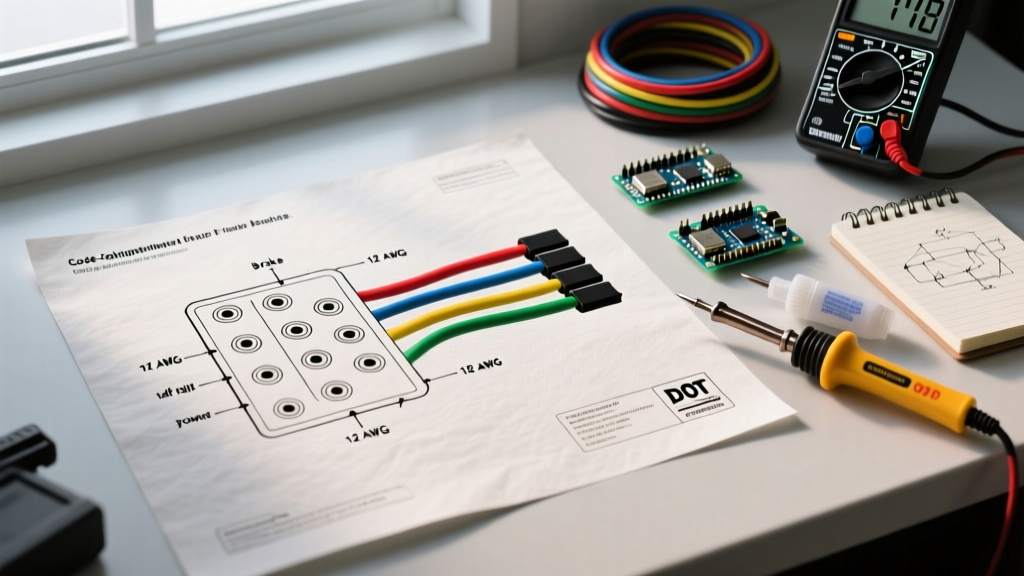
The 7-way RV blade connector is the undisputed standard for trailers equipped with electric brakes. Governed by the SAE J286 standard, this connector assigns specific functions and wire colors to each pin. Deviating from these color codes is a primary cause of cross-wired circuits and blown fuses during roadside inspections.
| Pin Location | Function | Standard Wire Color | Min. Wire Gauge | Circuit Protection |
|---|---|---|---|---|
| Pin 1 (Top Left) | System Ground (White) | White | 10 AWG | N/A (Direct to Frame) |
| Pin 2 (Top Right) | 12V Auxiliary / Battery Charge | Black | 10 AWG | 30A Auto-Reset Breaker |
| Pin 3 (Center) | Reverse Lights / Aux | Yellow | 16 AWG | 10A Fuse |
| Pin 4 (Bottom Left) | Left Turn / Stop Lamp | Red | 14 AWG | 15A Fuse |
| Pin 5 (Bottom Center) | Tail / Running / Marker Lights | Green | 14 AWG | 15A Fuse |
| Pin 6 (Bottom Right) | Right Turn / Stop Lamp | Brown | 14 AWG | 15A Fuse |
| Pin 7 (Top Center) | Electric Trailer Brakes | Blue | 10 AWG | 30A - 40A Auto-Reset Breaker |
Note: While many pre-packaged harnesses use 12 AWG for the blue brake wire, safety experts and etrailer wiring guidelines strongly recommend upgrading to 10 AWG for the brake and ground circuits to handle inrush currents and prevent voltage drop over long runs.
Wire Gauge Selection & Voltage Drop: The #1 Safety Failure Point
The most common edge-case failure in electric trailer braking is weak braking force caused by voltage drop. Standard 10x2-1/4 inch electric brake magnets (such as those found in Dexter Nev-R-Lube assemblies) draw approximately 3.0 to 3.5 amps each at 12V. A dual-axle trailer (4 brakes) draws 12 to 14 amps continuously, with an initial inrush current that can spike to 25 amps.
Calculating Voltage Drop for Brake Magnets
If you use a standard 12 AWG wire for a 25-foot run from the tow vehicle's brake controller to the trailer axles, the resistance of the copper wire will cause a significant voltage drop. The formula for single-phase DC voltage drop is:
VD = (2 x K x I x L) / CM
- K = Specific resistance of copper (12.9 ohms per mil-foot)
- I = Current in amps (14A continuous)
- L = Length of wire in feet (50 feet total round-trip)
- CM = Circular mils of the wire (6,530 for 12 AWG; 10,380 for 10 AWG)
Using 12 AWG wire, the voltage drop is approximately 1.38V, meaning your brake magnets only receive 10.6V, resulting in a 15% loss in braking torque. By upgrading the blue brake wire and the white ground wire to 10 AWG, the voltage drop falls to 0.87V, ensuring your brakes receive the full 11.1V+ required for maximum stopping power.
Breakaway Switch Wiring: Code Requirements and Fail-Safe Integration
Federal and state DOT regulations mandate that any trailer with a Gross Vehicle Weight Rating (GVWR) over 3,000 lbs must be equipped with a functional breakaway braking system. This system must be capable of applying full braking force for a minimum of 15 minutes if the trailer separates from the tow vehicle.
Code Compliance Warning: The breakaway system MUST have its own dedicated power source. It cannot draw power from the tow vehicle's 7-way plug, as a severance of the umbilical cord would render the brakes completely inoperative during a breakaway event.
Step-by-Step Breakaway Wiring Integration
- Power Source: Install a 12V 5Ah Sealed Lead Acid (SLA) battery in a weatherproof breakaway box mounted to the trailer tongue.
- Charge Line: Run a 12 AWG wire from the 12V Auxiliary pin (Pin 2, Black wire) on the 7-way plug through a 20A inline resettable breaker to the positive terminal of the breakaway battery.
- Switch Integration: Connect the positive terminal of the breakaway battery to one terminal of the breakaway switch. Connect the second terminal of the switch directly to the Blue (Brake) wire on the trailer side of the wiring harness.
- Grounding: Connect the negative terminal of the breakaway battery to the trailer frame using a 12 AWG white wire and a star washer to ensure a bare-metal connection.
When the lanyard is pulled, the switch closes, sending 12V directly from the dedicated battery to the brake magnets, bypassing the tow vehicle entirely.
Circuit Protection: Why Auto-Reset Breakers Beat Standard Fuses
A frequent code violation found during commercial DOT inspections is the use of standard automotive blade fuses for the main electric brake feed and 12V auxiliary charge lines. Electric brake magnets are highly inductive loads. When the brake controller sends a PWM (Pulse Width Modulation) signal, the initial inrush current can easily blow a standard 20A or 30A blade fuse, leaving the trailer with zero braking capacity.
The Solution: Always use Type 1 or Type 2 Auto-Resetting Circuit Breakers (such as the Bussmann 181-Series or Littelfuse MegaFuse resettable breakers) rated for 30A or 40A on the blue brake wire and the black auxiliary wire. These breakers handle the micro-second inrush spikes without tripping, but will safely open the circuit in the event of a sustained dead short (e.g., a chafed wire touching the trailer frame).
Common Code Violations and Edge-Case Failure Modes
Even with a correct wiring diagram for electric trailer brakes, poor execution leads to dangerous edge cases. Review this troubleshooting matrix to ensure your build passes safety inspections.
| Symptom / Failure Mode | Probable Cause | Safety & Code Implication | Required Fix |
|---|---|---|---|
| Brakes pulse weakly; lights dim when braking. | Relying on the hitch ball for the ground return path. | High resistance ground causes voltage drop and erratic brake controller behavior. | Run a dedicated 10 AWG white ground wire from Pin 1 directly to a sanded, bare-metal spot on the trailer frame. |
| Breakaway battery is constantly dead. | Charge line wired without an inline breaker, or wired to the brake pin instead of the 12V aux pin. | Fails DOT inspection; trailer will not stop in a separation event. | Verify Pin 2 (Black) is feeding the battery via a 20A auto-reset breaker. |
| Brake controller displays "Overload" or "Short". | Undersized wiring chafing against the axle, or moisture inside a cracked brake magnet housing. | Fire hazard; complete loss of trailer braking. | Inspect all undercarriage wiring for loom protection. Replace cracked Dexter or Lippert brake magnets immediately. |
| Trailer brakes lock up when connecting to a Ford/Chevy factory controller. | Pinout mismatch on the tow vehicle side (e.g., Ford uses a different reverse/brake pin layout on some older models). | Extremely dangerous; brakes apply at full force while driving. | Test the tow vehicle's 7-way receptacle with a digital multimeter and a circuit tester before connecting the trailer. |
Final Pre-Tow Compliance Checklist for 2026
Before hitting the road, run through this rapid safety checklist to ensure your electrical braking system meets current highway safety standards:
- Multimeter Test: Verify 11.5V+ at the trailer-side blue wire when the tow vehicle's manual override slider is fully engaged.
- Breakaway Test: Pull the breakaway lanyard. The trailer wheels should lock up completely. Re-insert the pin immediately to prevent overheating the magnets.
- Connector Tension: Ensure the 7-way plug has tight pin tension. Loose pins cause arcing, which melts the housing and creates a fire hazard.
- Wire Loom: Confirm all wiring within 2 feet of the brake assemblies is encased in split-loom tubing and secured with UV-resistant zip ties to prevent abrasion against the suspension.
By treating your trailer's electrical system with the same rigor as its mechanical components, you ensure compliance with federal safety standards and, more importantly, protect yourself and others on the road.