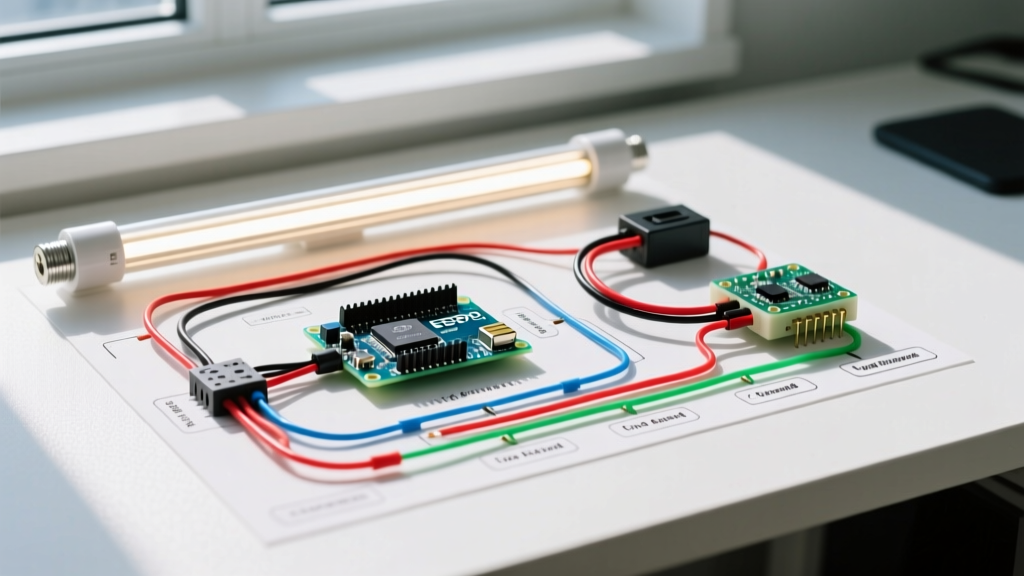

The Definitive Guide to Type B LED Tube Wiring
Upgrading from fluorescent to LED lighting is one of the highest-ROI electrical retrofits available in 2026. However, the most common point of failure in these projects is improper socket wiring. Understanding the correct wiring diagram for LED tube lights—specifically for Type B (Direct Wire / Ballast Bypass) tubes—is critical to preventing short circuits, tripped breakers, and premature diode failure.
While Type A (Plug-and-Play) tubes rely on the existing fluorescent ballast, ballasts are notorious for failing every 3 to 5 years and parasitically wasting 10% to 15% of the system's energy. According to the U.S. Department of Energy's Solid-State Lighting program, bypassing the ballast entirely (Type B) eliminates this point of failure and maximizes lumens-per-watt efficiency. This walkthrough details the exact step-by-step procedure for wiring single-ended Type B LED T8 tubes, the industry standard for commercial and residential retrofits.
LED Tube Classification Matrix
Before cutting a single wire, verify your tube type. The wiring diagram for LED tube lights changes drastically depending on the internal driver architecture.
| Tube Type | Power Source | Ballast Required? | Wiring Complexity | 2026 Market Status |
|---|---|---|---|---|
| Type A | Ballast Output | Yes (Must be compatible) | Low (Plug & Play) | Declining (Ballast dependency) |
| Type B | Line Voltage (120-277V) | No (Bypassed) | Medium (Rewire sockets) | Industry Standard / Preferred |
| Type C | External LED Driver | No (Replaced by Driver) | High (New driver install) | Niche (High-bay / Dimming) |
| Type A/B | Ballast OR Line Voltage | Optional | Medium | Transitional / Inventory clearing |
Critical Safety & Code Compliance
Working with 120V/277V line voltage requires strict adherence to safety protocols. OSHA's Control of Hazardous Energy (Lockout/Tagout) standards mandate that the circuit breaker must be locked out and tagged before opening any fixture enclosure. Furthermore, NEC Article 410, as outlined by the National Fire Protection Association, dictates specific fixture wiring methods and wire temperature ratings. Always use 18 AWG or 16 AWG stranded THHN/TEWN fixture wire rated for at least 90°C.
The #1 DIY Mistake: Shunted vs. Non-Shunted Tombstones
WARNING: Most modern single-ended Type B LED tubes require non-shunted tombstones (sockets) on the live end. If you wire line voltage into a shunted tombstone, the internal brass jumper will connect the Line and Neutral together, resulting in an immediate dead short, a blown breaker, and potentially a melted socket.
How to identify your tombstones:
- Shunted (e.g., Leviton 13111): Features a single internal brass contact connecting both pin holes. Used for rapid-start fluorescent ballasts. Must be replaced for single-ended Type B wiring.
- Non-Shunted (e.g., Leviton 13110): Features two isolated brass contacts. Each pin hole is electrically independent. Required for single-ended Type B wiring.
Step-by-Step Wiring Walkthrough: Single-Ended Type B
This diagram and walkthrough assume a standard 4-foot T8 fixture with two tombstones on the left (Line side) and two on the right (Neutral side), utilizing single-ended power delivery.
Step 1: LOTO and Ballast Extraction
- Turn off the breaker and verify zero voltage at the fixture using a CAT III multimeter (e.g., Klein Tools MM400).
- Remove the fluorescent tubes and the metal ballast cover.
- Cut all wires leading from the ballast to the tombstones, leaving about 2 inches of wire on the tombstone side.
- Disconnect the incoming Line (Hot) and Neutral wires from the ballast. Remove the ballast entirely to eliminate phantom weight and future rattle.
Step 2: Tombstone Verification and Replacement
- Use a multimeter in continuity mode to test the tombstones on the Line (Hot) end of the fixture.
- Place one probe in the left pin hole and the other in the right pin hole of the same tombstone. If the multimeter beeps (reads near 0.00 ohms), it is shunted.
- Pry out any shunted tombstones on the Line end and snap in new non-shunted replacements (Leviton 13110 or equivalent).
- Note: The Neutral end tombstones can remain shunted or non-shunted, as they will simply be jumpered together to complete the neutral return path.
Step 3: Routing Line and Neutral (The Wiring Diagram)
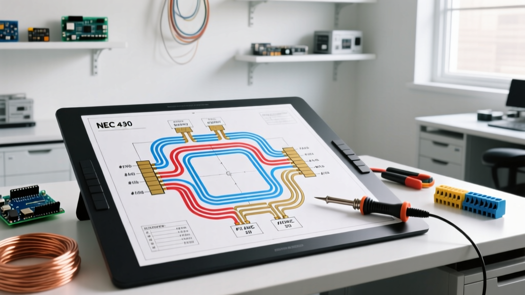
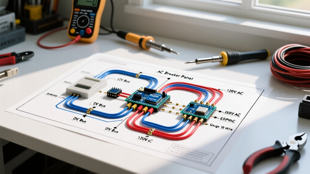
Follow this text-based schematic to wire the fixture directly to the AC mains:
[AC MAINS PANEL]
      |
      +--- [BLACK / HOT WIRE] -----------------------+--- [Wire Nut] --- [Jumper Wire] --- [Non-Shunted Tombstone 1A (Line)]
      |                                              |
      |                                              +--- [Wire Nut] --- [Jumper Wire] --- [Non-Shunted Tombstone 1B (Line)]
      |
      +--- [WHITE / NEUTRAL WIRE] -------------------+--- [Wire Nut] --- [Jumper Wire] --- [Tombstone 2A (Neutral)]
                                                     |
                                                     +--- [Wire Nut] --- [Jumper Wire] --- [Tombstone 2B (Neutral)]
- Wire the Line (Hot) End: Connect the incoming AC Black (Hot) wire to one pin of the first non-shunted tombstone. Run a short 18 AWG jumper wire from that same pin to the corresponding pin on the second non-shunted tombstone. Leave the other pins on these non-shunted tombstones completely empty.
- Wire the Neutral End: Connect the incoming AC White (Neutral) wire to one pin of the first tombstone. Run a jumper wire to the second tombstone. If using shunted tombstones here, you only need to connect to one pin hole, as the internal jumper handles the second pin.
- Grounding: Ensure the fixture's metal chassis remains bonded to the incoming bare copper ground wire. Do not disconnect the ground.
Step 4: Final Connections and Testing
- Secure all wire nuts with electrical tape (optional but recommended for commercial vibration environments).
- Neatly fold the wires into the fixture channel. Ensure no bare copper is exposed outside the wire nuts.
- Install the LED tube. Look for the "L" or "Input" marking on one end of the tube glass. This marked end must be inserted into the tombstones you wired to the Line (Hot) voltage.
- Restore power at the breaker. The tube should illuminate instantly with no flickering or humming.
Troubleshooting Common Failure Modes
| Symptom | Probable Cause | Diagnostic & Fix |
|---|---|---|
| Breaker trips instantly upon power-on | Dead short. Hot and Neutral wired to the same shunted tombstone, or Hot wired to both ends of a single-ended tube. | Verify tombstone continuity. Ensure Hot is only on one physical end of the fixture. |
| Tube flickers or strobes | Loose neutral connection, or attempting to run a Type B tube on an old, failing magnetic ballast (misidentified as Type A). | Check wire nut torque. Remove ballast entirely if present. |
| Only half the tube illuminates | Internal driver failure due to voltage spike, or tube inserted backward (Neutral end on Hot tombstones) in some strict-polarity models. | Swap tube orientation. If it persists, the tube's internal IC driver is blown; replace under warranty. |
2026 Cost and ROI Breakdown
The economics of ballast bypass have only improved. In 2026, a high-CRI (90+), 15W Type B T8 LED tube costs between $3.50 and $5.50 in bulk. Replacing a failed magnetic or electronic fluorescent ballast costs $12 to $18 for the part alone, plus 20 minutes of labor. By executing the wiring diagram for LED tube lights detailed above, facility managers and DIYers eliminate the $15 ballast replacement cost permanently. For a standard 2-lamp fixture running 10 hours a day, the drop from 64W (two 32W T8s + ballast factor) to 30W (two 15W Type B LEDs) yields a 53% energy reduction, typically paying for the $10 total material investment in under 6 months at the current national average commercial electricity rate of $0.12/kWh.