
Why Modern Tow Vehicles Demand Breaker-Protected Trailer Wiring
When searching for a reliable wiring diagram for trailer lights, most DIYers only find basic 4-way flat schematics meant for lightweight utility trailers. However, if you are wiring a heavy-duty car hauler, a multi-axle RV, or a horse trailer with living quarters, tapping directly into your tow vehicle’s lighting circuits is a critical mistake. Modern trucks (including 2024-2026 models from Ford, GM, and Ram) utilize multiplexed CAN-bus Body Control Modules (BCMs) to manage exterior lighting. These solid-state BCMs are highly sensitive to overcurrent events and voltage backfeed. A short circuit in a cheap trailer taillight can instantly fry a $1,200 OEM BCM or trigger a dashboard limp-mode error.
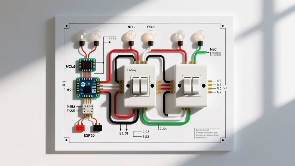
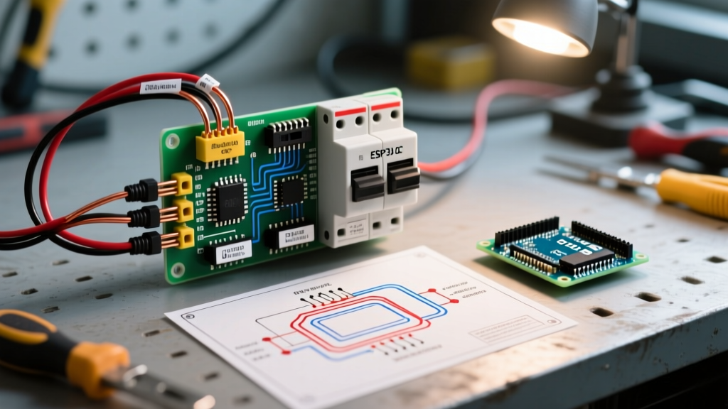
To prevent this, professional riggers use a dedicated DC breaker panel and relay isolation system. This guide provides a comprehensive, panel-integrated wiring diagram for trailer lights, ensuring your tow vehicle’s electronics remain protected while delivering stable, voltage-drop-free power to high-draw trailer accessories and LED lighting arrays.
Core Components for a Breaker-Protected Trailer System
Before mapping the circuit, you must source marine-grade or RV-rated components capable of withstanding high-vibration, high-moisture environments beneath a trailer chassis or inside a tongue-mounted battery box.
- Blue Sea Systems ST Blade Fuse Block (Model 5025): A 6-circuit fused distribution block (~$45). This acts as the interior DC panel for your trailer’s lighting and auxiliary circuits.
- Bussmann 187-Series Waterproof Circuit Breakers: Unlike the standard 185-series, the 187-series features a marine-grade waterproof boot (~$28 each). Essential for tongue-mounted main power cutoffs.
- Curt 56226 7-Way RV Blade Connector: Heavy-duty molded plug with 8-foot pigtails (~$35). The 7-way standard is mandatory for separating electric brakes, 12V auxiliary charging, and isolated lighting circuits.
- Ancor Marine Grade Duplex Wire: Tinned copper resists galvanic corrosion. Budget roughly $1.40/ft for 10 AWG and $0.85/ft for 14 AWG.
- Optronics Thinline LED Marker Lights: Drawing only 0.05 amps per fixture compared to 2.5 amps for incandescent bulbs, these drastically reduce the load on your lighting breakers.
The 7-Way RV Standard: Circuit Mapping
According to eTrailer's comprehensive wiring guidelines, the 7-way RV blade connector (SAE J286 standard) is the backbone of heavy-duty trailer electrical systems. Here is how the pins map to your new DC breaker panel:
- Pin 1 (Ground): White wire. Must be bonded directly to the trailer frame and the negative busbar of your DC panel using a minimum 8 AWG wire.
- Pin 2 (Electric Brakes): Blue wire. Routes through a dedicated 30A breaker to the brake controller output.
- Pin 3 (Tail/Running Lights): Brown wire. Feeds the 10A fused circuit on the Blue Sea panel for all perimeter clearance lights.
- Pin 4 (12V Auxiliary/Charge): Black wire. Routes through a 40A waterproof Bussmann breaker to charge the trailer’s auxiliary battery or power interior DC appliances.
- Pin 5 (Right Turn/Stop): Green wire. Feeds a 15A fused circuit on the panel.
- Pin 6 (Left Turn/Stop): Yellow wire. Feeds a 15A fused circuit on the panel.
- Pin 7 (Reverse Lights): Purple wire. Feeds a 10A fused circuit for rear floodlights or backup cameras.
Wire Gauge and Breaker Sizing Matrix
Adhering to proper wire gauge limits is non-negotiable to prevent voltage drop and thermal events. The FMCSA lighting and reflector regulations mandate that all commercial and heavy-duty trailer circuits maintain sufficient voltage to achieve minimum candela ratings at the bulb. Use this matrix for runs up to 25 feet from the 7-way plug to the DC panel:
| Circuit Function | Max Expected Load (LED) | Wire Gauge (AWG) | Breaker / Fuse Size |
|---|---|---|---|
| Tail / Running Lights | 4 Amps | 14 AWG | 10A (Blade Fuse) |
| Left / Right Stop & Turn | 8 Amps | 12 AWG | 15A (Blade Fuse) |
| Reverse / Aux Floods | 10 Amps | 12 AWG | 15A (Blade Fuse) |
| Electric Brakes (Dual Axle) | 16 Amps | 10 AWG | 20A (Auto-Reset Breaker) |
| 12V Aux Charge Line | 30 Amps | 8 AWG | 40A (Waterproof Breaker) |
Step-by-Step Panel Installation & Wiring Flow
Step 1: Mount the DC Distribution Panel
Locate a dry, elevated area inside the trailer’s front storage bay or tongue box. Mount the Blue Sea ST Blade Fuse Block and a companion negative busbar using stainless steel hardware. Ensure you have at least 6 inches of clearance above the panel for wire routing and fuse removal.
Step 2: Install the Main Power Cutoff
Run the 12V Auxiliary (Black) wire from the 7-way plug to a Bussmann 187-Series 40A waterproof breaker mounted on the exterior tongue. From the breaker's load side, run 8 AWG tinned wire to the trailer’s auxiliary deep-cycle battery positive terminal, and branch off to the Blue Sea panel’s main positive input.
Step 3: Route Lighting Circuits Through Fuses
Do not run the brown (tail), green (right), and yellow (left) wires directly to the lights. Instead, route them into the trailer’s interior bay and land them on the positive busbar of the Blue Sea panel. From the fused outputs of the panel, run new 14 AWG wires out to the individual Optronics LED fixtures. This ensures that a short in a rear marker light will only blow a $2 ATC blade fuse inside the panel, rather than blowing the tow vehicle’s main BCM fuse or melting the 7-way plug.
Step 4: Establish a True Chassis Ground
A common failure point in trailer wiring is relying on the hitch ball for grounding. According to Blue Sea Systems' circuit protection guidelines, all high-current DC systems require a dedicated ground return wire. Run a dedicated 10 AWG white ground wire from the 7-way plug to the negative busbar on your DC panel, and bond that busbar to the trailer frame using a self-tapping star-washer screw driven into bare, unpainted steel.
Expert Tip: Never use standard automotive crimp connectors on a trailer. The vibration and road salt will cause capillary corrosion within weeks. Use marine-grade heat-shrink crimp terminals with an internal adhesive lining that melts and seals the wire strands upon heating.
Common Failure Modes and Troubleshooting
Even with a perfect wiring diagram for trailer lights, environmental factors can introduce faults. Here is how to diagnose issues in a breaker-protected system:
Symptom: Tow Vehicle Dashboard Displays 'Trailer Wiring Fault'
The Cause: Modern trucks send a low-voltage pulse down the lighting circuits during startup to check for continuity. If your trailer uses ultra-low-draw LED lights, the truck’s BCM may interpret the low resistance as a 'burnt out bulb' or an open circuit. The Fix: Install a 6-way trailer wiring adapter with built-in load resistors (such as the Curt 57003), or solder 10-ohm, 50-watt ceramic resistors in parallel with your LED stop/turn circuits to simulate incandescent loads.
Symptom: 7-Way Plug Melting on the Auxiliary Pin
The Cause: Voltage drop and high resistance at the pin connection. If you are pulling 30 amps through the 12V auxiliary pin to charge a depleted trailer battery over a long drive, the standard brass pins can overheat. The Fix: Upgrade to a heavy-duty, oversized 7-way plug with solid copper pins. Ensure the wire crimp at the back of the plug is soldered and sealed, not just mechanically crimped. Limit auxiliary charge current to 20A using a DC-DC charger (like a Victron Orion 12/12-30) rather than a direct, unregulated wire run.
Symptom: Dim Taillights When Brakes are Applied
The Cause: Backfeed through a dual-filament bulb or a shared ground path that is corroded. When the high-current brake circuit activates, it seeks the path of least resistance, backfeeding into the running light circuit. The Fix: Verify that every single light fixture has its own dedicated ground wire routed back to the main negative busbar. Do not rely on 'grounding through the mounting screws' to the aluminum or steel skin of the trailer.
Final Safety Inspections
Before taking your newly wired trailer on the road, perform a voltage drop test. With the tow vehicle running and all trailer lights illuminated, use a digital multimeter to measure the voltage at the trailer’s DC panel positive busbar. It should read no less than 12.8V. If it reads below 12.2V, you have excessive resistance in the 7-way plug or the main ground wire, which will eventually lead to breaker tripping or BCM failure. By treating your trailer’s electrical system with the same respect as a residential DC solar panel or marine house bank, you guarantee years of safe, fault-free towing.