
Decoding the Dayton Electric Motor Wiring Schematic for Diagnostics
Dayton electric motors, widely distributed by Grainger, are the workhorses of commercial HVAC, agricultural compressors, and industrial blowers. When a Dayton motor fails to start, hums loudly, or trips a breaker, the Dayton electric motor wiring schematic is your most critical diagnostic tool. Rather than blindly swapping out $40 start capacitors or $150 centrifugal switches, a systematic approach using the factory schematic isolates the exact failure point in minutes.
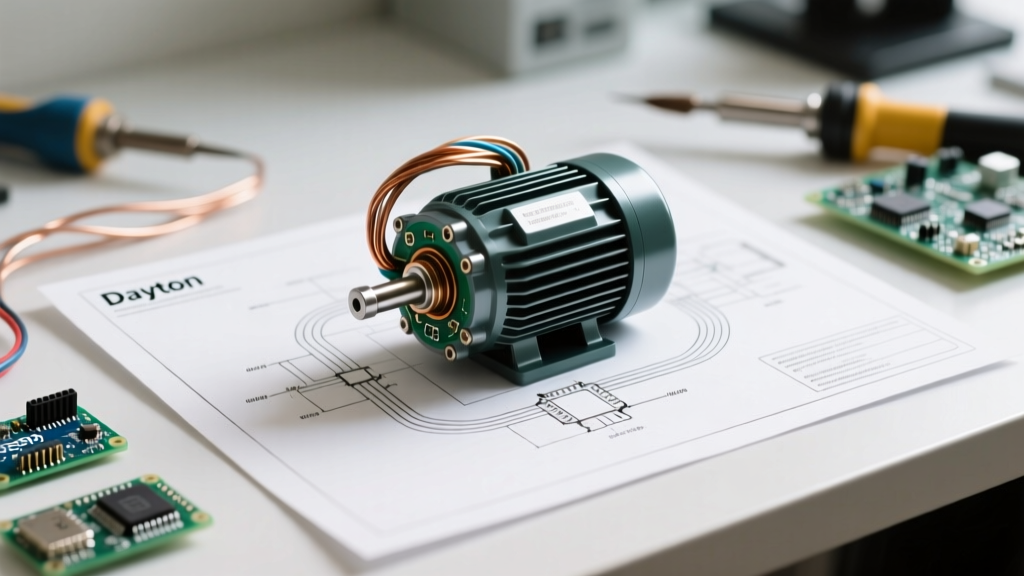
As of 2026, Dayton's lineup heavily features NEMA-standardized single-phase and three-phase designs. While the physical nameplate provides voltage and amperage data, it is the internal wiring diagram—usually tucked inside the conduit box cover—that reveals the logical flow of current through the start windings, run windings, thermal overloads, and switching mechanisms.
Anatomy of a Dayton Single-Phase Schematic
To troubleshoot effectively, you must first translate the schematic's symbolic language into physical motor components. Most Dayton single-phase motors (like the popular Dayton 6K582 1.5 HP split-phase or the Dayton 3N442 Capacitor-Start/Capacitor-Run models) utilize standardized NEMA T-lead designations.
Critical Schematic Symbols & Tracing Points
- T-Leads (T1 through T8): Dual-voltage motors (115/230V) use eight leads. The schematic shows how T-leads are paralleled for 115V and placed in series for 230V. Tracing continuity between these leads is the first step in identifying open windings.
- Centrifugal Switch (CS): Represented by a mechanical linkage symbol tied to the motor shaft. In a failed-start scenario, the schematic tells you exactly which T-leads (usually T5 and T8) route power through this switch to the start winding.
- Thermal Overload Protector (OL): Depicted as a bimetallic strip symbol in series with the main run winding. If a motor is completely dead (no hum, no continuity), the schematic guides you to test the OL terminals before condemning the motor windings.
- Start & Run Capacitors: Shown as parallel plate symbols. The schematic differentiates between the start capacitor (in series with the CS) and the run capacitor (permanently in circuit with the auxiliary winding).
Step-by-Step Troubleshooting Workflow
According to Fluke's motor troubleshooting guidelines, up to 40% of motor failures are electrical, yet many technicians misdiagnose the root cause by skipping schematic verification. Follow this exact workflow using a digital multimeter (DMM) like the Fluke 117 or 87V.
Step 1: Isolate and Lockout Power
Never troubleshoot a live Dayton motor. Disconnect all line voltage (L1 and L2) and verify zero energy with your DMM. Remove the conduit box cover and locate the wiring schematic. Take a photo of the current wiring configuration before disconnecting any wire nuts or spade terminals.
Step 2: Test the Thermal Overload (OL)
Locate the OL symbol on the schematic. In most Dayton PSC (Permanent Split Capacitor) and split-phase motors, the OL is embedded in the winding bundle but pigtails out to the terminal board.
- Set your DMM to continuity or low ohms (Ω).
- Probe the OL input and output terminals.
- Expected Reading: Near 0.0 Ω (closed circuit).
- Failure Mode: Infinite resistance (OL). If open, wait 30 minutes for the bimetallic strip to cool and reset. If it remains open, the internal overload is blown, requiring a motor replacement or specialized rewind.
Step 3: Trace the Start vs. Run Windings
Using the schematic, identify the T-leads for the run winding (typically T1 and T4) and the start winding (typically T5 and T8). Disconnect the start capacitor and centrifugal switch wires to isolate the bare copper windings.
Expert Insight: In a standard Dayton split-phase motor, the start winding is wound with thinner wire and more turns than the run winding. Therefore, your DMM should read a higher resistance on the start winding (T5-T8) compared to the run winding (T1-T4). If the start winding reads lower resistance, you may be testing a specialized Dayton high-torque model, or the windings are shorted internally.
Multimeter Diagnostics: Expected Ohm Readings
The table below provides benchmark resistance readings for common 115/230V Dayton single-phase motors (ranging from 1/2 HP to 3 HP). Always consult your specific nameplate, but these ranges serve as a reliable diagnostic baseline.
| Test Points (Schematic Reference) | Circuit Component | Expected DMM Reading (Ohms) | Diagnostic Meaning |
|---|---|---|---|
| T1 to T4 | Main Run Winding | 1.2 Ω - 3.5 Ω | Healthy run circuit. Lower than 1.0 Ω indicates shorted turns. |
| T5 to T8 | Start Winding | 4.0 Ω - 9.0 Ω | Healthy start circuit. Infinite (∞) means a broken internal wire. |
| T1 to Ground (Chassis) | Winding Insulation | Infinite (∞) / OL | Good insulation. Any reading below 1 MΩ means a ground fault. |
| Across Start Capacitor Terminals | Start Capacitor | N/A (Use Capacitance Mode) | Must be within +10% / -5% of printed μF rating. |
| Centrifugal Switch (Stationary) | Switch Contacts | 0.1 Ω - 0.5 Ω | Clean contacts. High resistance causes voltage drop and starting failure. |
Real-World Failure Modes & Schematic Tracing
Let us apply the Dayton electric motor wiring schematic to two of the most common field complaints reported by HVAC and maintenance technicians.
Failure Mode 1: Motor Hums Loudly but Will Not Rotate
The Symptom: You apply 115V to L1 and L2. The motor draws locked-rotor amps (LRA), vibrates, and emits a 60Hz hum, but the shaft does not turn. Pushing the shaft manually causes it to run up to speed.
Schematic Trace: The hum indicates the run winding (T1-T4) is energized. The failure to self-start means the phase-shifted magnetic field is missing. Trace the schematic from the line voltage, through the centrifugal switch (CS), to the start capacitor, and into the start winding (T5-T8).
The Fix: 1. Test the start capacitor. A Dayton 2MDV6 (189-227 μF) replacement costs roughly $18. If the capacitor is bulging or reads outside the μF tolerance, replace it. 2. If the capacitor is good, inspect the centrifugal switch. The schematic shows the switch is normally closed at rest. If the contacts are pitted or the spring mechanism is jammed by dust, the start winding never receives current. Clean the contacts with fine emery cloth or replace the switch assembly ($30-$45).
Failure Mode 2: Motor Trips Breaker Instantly Upon Energization
The Symptom: The moment the contactor pulls in, the 20A branch circuit breaker trips violently.
Schematic Trace: Instantaneous tripping indicates a dead short or a severe ground fault. Using the schematic, isolate the main power path. Bypass the thermal overload temporarily for testing purposes only. Measure resistance from T1 to the motor casing (ground).
The Fix: If you read continuity to ground, the winding insulation has melted and shorted to the stator core. No capacitor or switch replacement will fix this. The motor is condemned. As noted by the NEMA MG 1 standards for motors and generators, operating a motor with compromised ground insulation poses a severe arc-flash and electrocution hazard. Replace the motor immediately.
Reversing Rotation Using the Schematic
A frequent troubleshooting task involves correcting a Dayton motor that is spinning in the wrong direction (e.g., a blower wheel pushing air backward). The wiring schematic explicitly details the reversal procedure.
To reverse a standard Dayton single-phase motor, you must reverse the polarity of the start winding relative to the run winding. The schematic will show a swap block or instruction: "To reverse rotation, interchange leads T5 and T8." Never swap T1 and T4 (the run winding) while leaving T5/T8 intact, as this can cause internal phasing issues in certain capacitor-run configurations. Always ensure the motor comes to a complete stop before reversing the contactor polarity, or the centrifugal switch will be destroyed by the counter-torque.
Frequently Asked Questions (FAQ)
Can I run a Dayton dual-voltage motor on 230V if the schematic shows 115V?
Yes, if the nameplate reads 115/230V. The schematic inside the conduit box will show two distinct wiring diagrams. For 230V, you will wire the run windings in series (connecting T2 to T3) and use T1, T4, T5, and T8 for the line and start circuits. Running a 115/230V motor on 230V halves the amperage draw, reducing voltage drop over long wire runs and improving overall efficiency, a principle supported by DOE motor systems best practices.
My Dayton schematic shows a 'red' wire, but my motor has a 'yellow' wire. Why?
Dayton sources motors from various OEMs (like Marathon, Leeson, and WEG). While the NEMA T-lead designations (T1-T8) remain standard, the physical insulation color codes can vary by manufacturing batch and OEM. Always trust the alphanumeric T-lead tags and the schematic logic over the wire colors. If T-tags are missing, use the resistance testing method outlined in the table above to identify the windings.
How do I test the run capacitor on a Dayton CSCR motor?
Unlike the start capacitor, the run capacitor (typically 5 μF to 15 μF) remains in the circuit continuously. Disconnect power, discharge the capacitor with a 20kΩ 5W resistor, and use your DMM's capacitance setting. If the reading is more than 10% below the printed rating, the dielectric fluid has degraded. A failing run capacitor causes the motor to draw high amps on the run winding, eventually tripping the internal thermal overload.