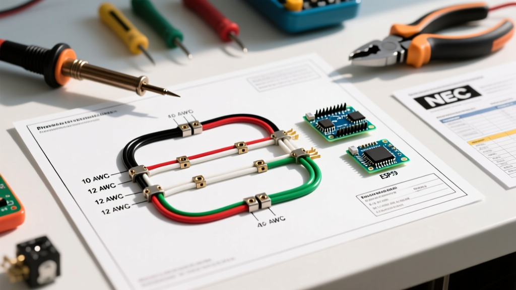

Installing a modern electric range or wall oven requires more than just plugging in a cord; it demands a precise understanding of electrical load, wire gauge, and National Electrical Code (NEC) color standards. Whether you are upgrading to a high-draw 2026 induction range or replacing a legacy unit, interpreting the wiring diagram for oven setups is critical for safety and performance. Misinterpreting terminal block mappings or undersizing your conductors can lead to tripped breakers, melted insulation, or severe fire hazards.
This comprehensive reference guide breaks down the exact wire gauges, color codes, and terminal configurations required for residential 240V oven circuits, ensuring your installation meets current NEC standards and operates flawlessly.
Decoding the Wiring Diagram for Oven Terminals
Before pulling any wire through a conduit or routing NM-B cable through your joists, you must understand the terminal block located on the back of the appliance. Most modern 4-wire electric ovens feature a 4-terminal block, though some older or specialized units may use a 3-terminal setup. Always consult the manufacturer's specific wiring diagram for oven models, as terminal layouts can vary between brands like GE, Whirlpool, and Bosch.
Standard 4-Terminal Block Mapping
- L1 (Hot 1): Connects to the Black wire. Carries 120V relative to neutral.
- L2 (Hot 2): Connects to the Red wire. Carries 120V relative to neutral, but is 180 degrees out of phase with L1, providing 240V across L1 and L2 for the heating elements.
- N (Neutral): Connects to the White wire. Carries the return current for 120V components like the oven light, control board, and convection fans.
- G (Ground): Connects to the Bare or Green wire. Provides a dedicated, low-impedance fault path back to the main panel.
Critical E-E-A-T Note: Under NEC 110.14(D), any termination on a circuit rated over 100A requires a calibrated torque tool. While most residential ovens fall under this threshold, manufacturers increasingly specify exact torque values (typically 12 to 18 in-lbs) for terminal block screws to prevent thermal cycling loosening and subsequent arcing.
Wire Gauge Selection: Matching AWG to Breaker Size
Selecting the correct American Wire Gauge (AWG) is dictated by the oven's maximum amperage draw and the rating of the circuit breaker. In 2026, with the rise of advanced induction ranges featuring integrated air-fry and rapid-boil technologies, many new ovens require 50A circuits rather than the legacy 40A standard.
| Oven Amperage | Breaker Size (Double Pole) | Minimum Copper Wire Gauge (NM-B / THHN) | Standard Receptacle Type | Approx. 2026 Material Cost |
|---|---|---|---|---|
| Up to 30A | 30A (e.g., Square D QO230) | 10 AWG (10/3 with ground) | NEMA 14-30R | $1.85 - $2.20 / ft |
| 31A to 40A | 40A (e.g., Siemens Q240) | 8 AWG (8/3 with ground) | NEMA 14-50R | $2.40 - $2.90 / ft |
| 41A to 50A | 50A (e.g., Square D QO250) | 6 AWG (6/3 with ground) | NEMA 14-50R | $3.15 - $3.80 / ft |
Note: Aluminum wire is strongly discouraged for residential indoor appliance branch circuits due to higher resistance, thermal expansion issues, and the necessity of using anti-oxidant paste and CO/ALR rated terminations.
NEC Color Code Standards for 240V Range Circuits
Adhering to standard color codes is not just a best practice; it is a strict requirement under the NFPA 70 (National Electrical Code). Consistent color coding ensures that future electricians or homeowners can safely troubleshoot the circuit.
Mandatory Conductor Colors
- Black (Ungrounded / Hot): Must be used for the first ungrounded conductor (L1). Never use black for a neutral or ground.
- Red (Ungrounded / Hot): Must be used for the second ungrounded conductor (L2). In a standard 6/3 or 8/3 NM-B cable, the red and black wires are the 240V pair.
- White or Gray (Grounded / Neutral): Reserved exclusively for the neutral conductor. If you are pulling individual THHN wires in a conduit, you must use white or gray insulation for the neutral.
- Bare Copper or Green (Equipment Grounding Conductor): Used solely for safety grounding. It should never carry current during normal operation.
The 3-Wire vs. 4-Wire Configuration Shift
One of the most common points of confusion when reading a wiring diagram for oven installations in older homes is the discrepancy between 3-wire and 4-wire setups. Prior to the 1996 NEC revision, ranges and dryers were permitted to use a 3-wire configuration where the appliance frame was bonded to the neutral wire. This was inherently dangerous: if the neutral wire broke or disconnected, the metal chassis of the oven could become energized at 120V, posing a lethal shock hazard.
Modern 4-Wire Mandate (NEC Article 250.140)
Today, all new construction and major renovations require a 4-wire setup, separating the neutral (current-carrying) and the ground (fault-clearing) paths. The Electrical Safety Foundation International (ESFI) strongly advises upgrading any active 3-wire range circuits to 4-wire configurations during appliance replacements.
Removing the Bonding Strap
If you are connecting a new 4-wire range cord to an oven that shipped with a 3-wire cord pre-installed, you must remove the copper bonding strap (or bonding jumper wire) that connects the neutral terminal to the metal chassis. Failing to remove this strap on a 4-wire circuit creates a parallel neutral path, causing current to flow on the ground wire and potentially tripping GFCI/AFCI breakers or creating a shock hazard.
Voltage Drop and Long-Run Adjustments
The wire gauges listed in the table above assume a standard run of less than 50 feet from the main service panel to the receptacle. If your oven is located in a large custom kitchen or an outdoor summer kitchen where the cable run exceeds 50 feet, you must account for voltage drop.
According to NEC informational notes, a maximum voltage drop of 3% on a branch circuit is recommended for optimal efficiency. For a 240V circuit, a 3% drop equates to 7.2 volts. If you are pulling a 50A circuit over a distance of 75 feet, standard 6 AWG copper will experience excessive voltage drop, causing the oven's control boards to malfunction or heating elements to underperform.
- Run up to 50 ft: Use 6 AWG Copper for 50A.
- Run 51 ft to 80 ft: Upsize to 4 AWG Copper for 50A.
- Run 81 ft to 110 ft: Upsize to 3 AWG or 2 AWG Copper for 50A.
Common Failure Modes & Troubleshooting
Even with a perfect wiring diagram for oven setups, installation errors can occur. Here are the most frequent failure modes identified by the U.S. Consumer Product Safety Commission (CPSC) and field electricians:
1. Control Board Flickering or Resetting
Cause: Loose neutral connection at the terminal block or the main panel. The control board requires a stable 120V reference between L1 and Neutral. If the neutral is loose, voltage fluctuates, causing the digital display to reboot during high-draw heating cycles.
Fix: Power down the breaker, verify the white wire is securely seated under the neutral terminal, and check the neutral bus bar in the main panel.
2. Breaker Trips Instantly Upon Turning On the Oven
Cause: A dead short, often caused by pinching the NM-B cable behind the oven during the push-in, damaging the insulation and allowing the hot conductor to contact the ground wire or metal chassis.
Fix: Inspect the entire cable run, particularly where it passes through framing or enters the junction box. Replace damaged cable sections; never rely on electrical tape for high-amperage 240V repairs.
3. Oven Receptacle Melting or Discoloration
Cause: Using a cheap, non-commercial grade NEMA 14-50R receptacle, or failing to torque the terminal screws to spec. High-draw induction ranges can pull continuous loads near 40A for extended periods, generating immense heat at high-resistance connections.
Fix: Replace the receptacle with a heavy-duty, industrial-grade model (e.g., Leviton 278-S00 or Hubbell 9450A) and ensure all wire terminations are torqued to the manufacturer's specified inch-pounds.
Summary Checklist for Oven Wiring
- Verify the oven's maximum ampacity on the manufacturer's nameplate.
- Install the correct double-pole breaker (e.g., 50A for most modern induction ranges).
- Pull the correct gauge NM-B or THHN wire (6 AWG for 50A).
- Ensure strict adherence to Black/Red/White/Bare color coding.
- Remove the neutral-to-chassis bonding strap for 4-wire installations.
- Torque all terminal screws to the manufacturer's specifications.