
The Critical Role of Wire Gauge in Trailer Brake Systems
When building or repairing a towing setup, understanding the wiring diagram for a trailer with electric brakes goes far beyond simply matching colors to pins. Electric trailer brakes are safety-critical, high-current devices. A standard 10x2.25-inch electric brake assembly draws between 3.0 and 3.5 amps at 12 volts. On a dual-axle trailer with four brakes, your brake circuit must reliably deliver 12 to 14 amps over a 20- to 30-foot cable run. If your wire gauge is undersized, voltage drop will starve the brake magnets, resulting in dangerously weak stopping power.
This comprehensive reference guide breaks down the 2026 RVIA (Recreation Vehicle Industry Association) standard 7-way blade pinout, precise AWG (American Wire Gauge) requirements, insulation standards, and real-world failure modes to ensure your trailer stops exactly when you need it to.
Standard 7-Way RV Blade: Pinout, Color Codes, and AWG Sizing
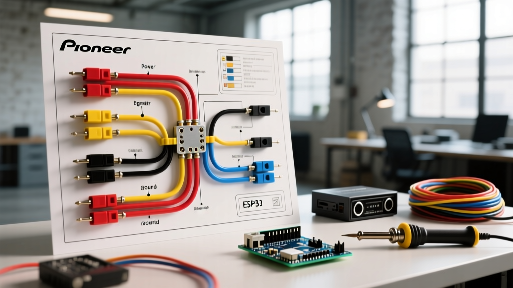
The 7-way RV blade connector is the undisputed standard for trailers equipped with electric brakes. While the physical plug is standardized, wire gauge selection must be tailored to the specific current draw of each circuit. Below is the definitive matrix based on Recreation Vehicle Industry Association (RVIA) guidelines.
| Pin | Function | RVIA Standard Color | Recommended AWG (Single Axle) | Recommended AWG (Dual Axle) |
|---|---|---|---|---|
| 1 | Ground (Chassis Return) | White | 10 AWG | 8 AWG |
| 2 | Electric Brakes | Blue | 12 AWG | 10 AWG |
| 3 | Tail / Running Lights | Green | 14 AWG | 14 AWG |
| 4 | Left Turn / Stop | Yellow | 14 AWG | 14 AWG |
| 5 | Right Turn / Stop | Brown | 14 AWG | 14 AWG |
| 6 | 12V Auxiliary / Reverse | Red | 12 AWG | 10 AWG |
| 7 | 12V Battery Charge | Black | 10 AWG | 10 AWG |
Never undersize the white ground wire. The ground wire carries the return current for all active circuits simultaneously. If your brakes (12A), tail lights (4A), and 12V fridge charge (10A) are running concurrently, the ground wire must handle 26+ amps. Using 14 AWG for the ground will cause severe voltage drops, resulting in dim lights and 'ghost braking' (brakes applying erratically due to floating grounds).
The Physics of Trailer Brakes: Calculating Voltage Drop
Why do we mandate 10 AWG for the blue brake wire on dual-axle trailers? The answer lies in voltage drop. According to Ohm's Law and the SAE International J1128 Standard for low-tension primary cable, copper wire has inherent resistance.
Real-World Voltage Drop Calculation
- Current Draw (I): 12.8 Amps (four 3.2A brake magnets)
- Wire Length (L): 25 feet one-way (50 feet total round-trip for the circuit)
- 12 AWG Copper Resistance: ~1.588 ohms per 1,000 feet
- 10 AWG Copper Resistance: ~0.998 ohms per 1,000 feet
Using 12 AWG Wire: Voltage Drop = (12.8A × 50ft × 1.588) / 1000 = 1.01 Volts. Your brakes receive 10.99V. This is acceptable but marginal under heavy load.
Using 10 AWG Wire: Voltage Drop = (12.8A × 50ft × 0.998) / 1000 = 0.63 Volts. Your brakes receive 11.37V, ensuring maximum magnetic clamping force.
As wire temperatures rise under continuous braking (like descending a mountain pass), resistance increases. Starting with 10 AWG provides a critical thermal buffer.
Wire Insulation Standards: GXL vs. SXL vs. THHN
Choosing the correct gauge is only half the battle; the insulation jacket determines the wire's lifespan in harsh undercarriage environments.
| Wire Type | Wall Thickness | Max Temp Rating | Best Application |
|---|---|---|---|
| GXL (General Cross-Linked) | Thin | 125°C (257°F) | Standard trailer wiring, flexible, fits easily into 7-way molded plugs. |
| SXL (Special Cross-Linked) | Standard | 125°C (257°F) | High-abrasion areas, routing near exhaust or sharp frame edges. |
| THHN (Building Wire) | Thick PVC/Nylon | 90°C (194°F) | DO NOT USE. Solid core or stiff stranded building wire cracks under trailer vibration and absorbs moisture. |
2026 Pricing Note: High-quality 10 AWG GXL primary wire typically costs between $0.85 and $1.15 per foot. Avoid cheap, unmarked PVC wires from overseas marketplaces, as they often use copper-clad aluminum (CCA) which has 40% higher resistance and will severely degrade brake performance.
Tow Vehicle Integration: Brake Controller Wiring
The trailer side is only half the equation. The tow vehicle must supply clean, modulated power to the blue brake circuit. In 2026, proportional brake controllers like the Tekonsha Prodigy P3 (Model 90195, ~$165) or the Curt Spectrum (Model 51175, ~$135, featuring Bluetooth app diagnostics) are the industry standard.
Brake Controller Pinout (Vehicle Side)
- White: Ground to vehicle chassis (must be sanded to bare metal).
- Black: 12V constant power directly to the vehicle battery via a 30A inline circuit breaker.
- Red: Stoplight switch signal (only powers on when the vehicle brake pedal is pressed).
- Blue: Output to the 7-way trailer connector (Pin 2).
Pro-Tip: Never splice the brake controller's red wire into a multiplexed CAN-bus taillight circuit on modern trucks (2020+ models). This will fry the controller's logic board. Always use a dedicated stoplight switch tap or the factory under-dash tow package port.
Step-by-Step Routing and Grounding Best Practices
According to towing safety guidelines referenced by the National Highway Traffic Safety Administration (NHTSA), improper wiring is a leading cause of trailer-related incidents. Follow these routing rules:
- The Dedicated Ground: Do not rely on the hitch ball for grounding. Run the 8 AWG or 10 AWG white wire directly from the 7-way plug to a dedicated grounding bolt on the trailer frame. Use a star washer and apply dielectric grease to prevent corrosion.
- Axle Chafing Protection: When running the blue brake wires down the axles to the backing plates, always use split-loom conduit. Secure it with UV-resistant zip ties every 8 inches. The most common cause of 'ghost braking' is the blue wire chafing against the axle tube, shorting to ground, and tricking the controller into applying the brakes.
- Heat Shrink Connections: Never use standard vinyl electrical tape or cheap crimp caps. Use nylon-insulated, adhesive-lined heat shrink butt connectors (12-10 AWG). The internal adhesive melts and seals out moisture, preventing the green corrosion that causes high-resistance joints.
Troubleshooting Matrix: Electric Brake Failures
When your brake controller throws an error code or the trailer pulls to one side, use this diagnostic matrix:
| Symptom | Probable Cause | Diagnostic Fix |
|---|---|---|
| Controller shows 'SH' (Short) error | Blue wire insulation chafed against frame/axle. | Inspect undercarriage with a mirror; wrap in split loom and friction tape. |
| Controller shows 'OL' (Overload) | Shorted brake magnet or melted wiring harness. | Disconnect trailer plug; measure resistance across pins 2 and 1. Should read 3-4 ohms per magnet. |
| Brakes feel weak / Trailer pushes truck | Severe voltage drop on blue or white wire. | Measure voltage at the trailer backing plate while an assistant holds the manual override. Must be >11.5V. |
| Lights dim when brakes are applied | Undersized white ground wire or corroded ground bolt. | Upgrade ground wire to 8 AWG; sand frame contact point to bare steel. |
Final Thoughts on 2026 Towing Standards
As trailers become heavier and tow vehicles integrate more complex multiplexed electrical systems, adhering strictly to the correct wiring diagram for a trailer with electric brakes is non-negotiable. By utilizing 10 AWG GXL wire for your brake and charge circuits, 8 AWG for the ground, and adhering to RVIA color codes, you eliminate the vast majority of electrical failures on the road. Always test your completed circuit with a digital multimeter and a dedicated 7-way circuit tester before hitting the highway.