
The Reality of 1-Ohm Mobile Audio Systems
Pushing a mobile audio amplifier to its absolute thermal and electrical limits requires more than just connecting wires; it demands a precise understanding of impedance, DC resistance, and power delivery. When enthusiasts search for a 1 ohm wiring diagram for subwoofers, they are typically chasing maximum wattage output. According to Ohm's Law and the power equation (P = V² / R), halving the impedance theoretically doubles the power output. However, dropping your final load to 1 ohm exponentially increases current draw (amperage) and heat generation within the amplifier's output stage.
In 2026, modern Class D monoblock amplifiers utilizing advanced PWM (Pulse Width Modulation) controllers and high-speed MOSFETs can handle 1-ohm loads far more gracefully than legacy Class AB designs. Yet, the margin for error is virtually zero. A poorly executed 1-ohm wiring job will result in immediate thermal throttling, clipping, or catastrophic failure of the amplifier's power supply board. This step-by-step walkthrough details the exact procedures, tools, and safety protocols required to wire dual voice coil (DVC) subwoofers to a stable 1-ohm final load.
⚠️ Critical Safety Callout: Amplifier Stability
Never attempt a 1-ohm load on an amplifier that is not explicitly rated for 1-ohm stability by the manufacturer. Check the owner's manual for the continuous RMS rating at 1 ohm, not the peak or dynamic rating. If your amplifier's lowest rated impedance is 2 ohms, wiring it to 1 ohm will trigger its internal protection circuitry or melt the output traces.
Bill of Materials & System Specifications
To demonstrate this walkthrough, we are using a high-output SPL (Sound Pressure Level) configuration common in competitive and enthusiast builds. Pricing reflects average 2026 market rates for premium Oxygen-Free Copper (OFC) and reliable amplification.
| Component | Specific Model / Spec | Estimated Cost | Role in System |
|---|---|---|---|
| Amplifier | Skar Audio RP-3500.1D (Class D Monoblock) | $349.99 | 1-Ohm Stable Power Source (3,500W RMS) |
| Subwoofers | 2x JL Audio 12W6v3-D4 (Dual 4-Ohm DVC) | $899.98 | Transducers (600W RMS each) |
| Power Wire Kit | 1/0 AWG OFC Elite Kit (with ANL Fuse) | $245.00 | Main current delivery from battery |
| Speaker Wire | 12 AWG OFC Stranded Copper | $45.00 | Low-resistance path to voice coils |
| Testing Tool | Fluke 117 True-RMS Digital Multimeter | $210.00 | Verifying DC Resistance (Re) |
Step-by-Step Walkthrough: Wiring Two 4-Ohm DVC Subs to 1 Ohm
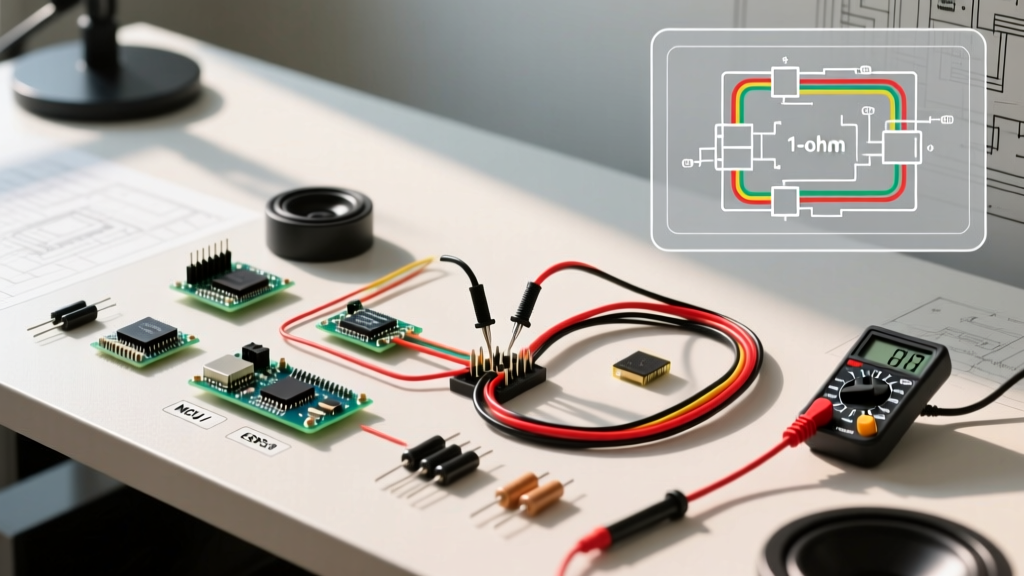
The most common and efficient method to achieve a 1-ohm final load is using two Dual 4-Ohm Voice Coil (DVC) subwoofers. This requires a series-parallel configuration: wiring the coils on each individual subwoofer in parallel (yielding 2 ohms per sub), and then wiring the two subwoofers in parallel at the amplifier terminals (yielding 1 ohm total).
Step 1: Verify Voice Coil DC Resistance (Re)
Before cutting any wire, you must verify the health and exact resistance of your voice coils. Nominal impedance (4 ohms) is an AC measurement that varies with frequency. Your multimeter measures DC resistance (Re), which will always read lower than the nominal rating. According to fundamental electrical impedance principles, a healthy 4-ohm voice coil should read between 3.2 and 3.8 ohms on a multimeter.
- Set your Fluke 117 to the Ohms (Ω) setting.
- Touch the probes together to measure lead resistance (usually 0.2Ω). Subtract this from your final reading.
- Place the probes on the positive and negative terminals of Coil 1 on Subwoofer A. Record the value (e.g., 3.4Ω).
- Repeat for Coil 2 on Subwoofer A, and both coils on Subwoofer B.
- Edge Case: If any coil reads "OL" (Open Loop) or near 0.0Ω (Short Circuit), the subwoofer is defective and must be replaced before proceeding.
Step 2: Intra-Subwoofer Parallel Wiring (Coils to Coils)
Now, we wire the two coils on each individual subwoofer together in parallel. This halves the impedance of each subwoofer from 4 ohms down to 2 ohms.
- Subwoofer A: Run a jumper wire from the Positive terminal of Coil 1 to the Positive terminal of Coil 2. Run a second jumper from the Negative terminal of Coil 1 to the Negative terminal of Coil 2.
- Subwoofer B: Repeat the exact same process. Positive to Positive, Negative to Negative.
- Pro Tip: Use 12 AWG OFC wire with closed-loop spade connectors. Crimp the connectors using a dedicated hex-crimp tool (like the Knipex ErgoCrimp) to ensure a gas-tight connection. Soldering is an alternative, but high-quality mechanical crimps withstand the intense vibrations of a subwoofer enclosure better over time.
Step 3: Inter-Subwoofer Parallel Wiring (Amp to Subs)
With both subwoofers now presenting a 2-ohm load individually, wiring them together in parallel at the amplifier will result in the final 1-ohm load (2Ω / 2 = 1Ω).
- Run your main 12 AWG speaker wire from the amplifier's positive terminal to the positive terminal of Coil 1 on Subwoofer A.
- Daisy-chain a second wire from that same positive terminal on Subwoofer A to the positive terminal on Subwoofer B.
- Repeat the process for the negative terminals, running from the amplifier's negative terminal to Sub A, and daisy-chaining to Sub B.
- Ensure all amplifier set-screws are tightened to the manufacturer's specified torque (typically 40-50 in-lbs) to prevent arcing under high current draw.
Impedance Configuration Matrix
If your hardware differs from the walkthrough above, use this matrix to determine your final load. Mismatching these will result in immediate amplifier protection faults. For more complex multi-sub configurations, the Crutchfield Car Audio Learning Center offers excellent interactive calculators.
| Subwoofer Configuration | Voice Coil Type | Wiring Method | Final Impedance |
|---|---|---|---|
| 1 Subwoofer | Dual 2-Ohm DVC | Coils in Parallel | 1 Ohm |
| 2 Subwoofers | Dual 4-Ohm DVC | Coils Parallel / Subs Parallel | 1 Ohm |
| 4 Subwoofers | Single 4-Ohm SVC | All Subs in Parallel | 1 Ohm |
| 2 Subwoofers | Dual 2-Ohm DVC | Coils Series / Subs Parallel | 2 Ohms (Safe Fallback) |
Critical Failure Modes & System Upgrades
Wiring the subwoofers correctly is only 50% of the battle. A 1-ohm system drawing 3,500 watts will pull upwards of 300 amps of current from your vehicle's electrical system at peak transients. If you ignore the electrical infrastructure, you will encounter the following failure modes:
1. Severe Voltage Drop and Headlight Dimming
At 1 ohm, if your vehicle's voltage drops below 12.0V, the amplifier will enter protection mode or produce heavily clipped, distorted output. Solution: You must perform the "Big 3" electrical upgrade using 1/0 AWG OFC wire. This involves upgrading the alternator to chassis ground, battery negative to chassis ground, and alternator positive to battery positive. For systems exceeding 2,000W RMS, upgrading to a high-output alternator (e.g., Mechman 240A or 320A) is mandatory.
2. Amplifier Thermal Throttling
Even high-end Class D amplifiers generate significant heat at 1 ohm due to internal resistance and switching losses. If the amplifier is mounted in a sealed trunk or under a seat without airflow, it will thermally throttle, cutting power by up to 75% to save the MOSFETs. Solution: Mount the amplifier in the cabin or a vented false floor, and ensure at least 2 inches of clearance around the heat sink fins. Consider adding a 12V PC fan directed at the fins for enclosed spaces.
3. Clipping and Voice Coil Burnout
Setting the gain on a 1-ohm system by "ear" is a guaranteed way to destroy your subwoofers. When an amplifier clips, it sends a DC square wave to the voice coil, which lacks the cooling effect of AC frequency movement, melting the copper winding in seconds. Solution: Use a digital oscilloscope or a dedicated distortion detector (like the SMD DD-1). Play a 40Hz test tone at 0dB, disconnect the speakers, and adjust the amplifier gain until the oscilloscope shows a clean sine wave just before the peaks flatten out. The Skar Audio Tech Tips blog provides excellent video tutorials on setting gain with a DD-1 for their RP-series amplifiers.
Expert FAQ: 1-Ohm Wiring Nuances
Q: Can I wire a 1-ohm load using CCA (Copper Clad Aluminum) wire?
A: Absolutely not. CCA wire has roughly 40% higher electrical resistance than pure OFC. At 1 ohm and high amperage, CCA wire will act as a resistor, dropping voltage, generating excess heat, and potentially melting the insulation. Always use 100% Oxygen-Free Copper for 1-ohm builds.
Q: My amplifier says "1 Ohm Stable" but it keeps shutting off during heavy bass hits. Why?
A: This is almost always a voltage drop issue, not an impedance issue. When the bass hits, current demand spikes. If your battery/alternator cannot supply the amperage, the voltage at the amp's terminals drops below 10V, triggering the amp's under-voltage protection. Check your connections for corrosion and verify your alternator output under load.
Q: Is it better to run two 2-ohm amps bridged, or one 1-ohm stable monoblock?
A: In 2026, a high-quality 1-ohm stable monoblock is vastly superior. Bridging two 2-channel amps introduces phase-matching issues, requires complex signal splitting, and doubles the points of failure. A dedicated monoblock is engineered with a unified power supply specifically designed to handle the massive current draw of a 1-ohm load safely.