
The Critical Role of Precision in Trailer Brake Wiring
Electric trailer brakes are non-negotiable for any rig exceeding 1,500 lbs GVWR. A flawed trailer electric brake wiring diagram implementation doesn't just mean blown fuses or dim lights; it means a 5,000-lb load pushing your tow vehicle downhill on a 6% grade. In 2026, with modern integrated brake controllers and advanced multiplexed tow vehicle electrical systems, the margin for error is smaller than ever.
This comprehensive walkthrough bypasses generic advice and dives into the exact wire gauges, circuit protection standards, and physical routing protocols required to build a fail-safe electric brake circuit from the tow vehicle's battery to the trailer axles.
Decoding the 7-Way RV Blade Standard
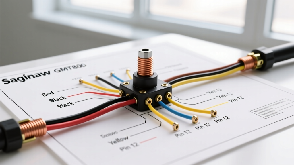
For electric brakes, the 7-way RV blade connector is the undisputed North American standard. While flat-4 connectors handle basic lighting, they lack the dedicated circuits required for brake actuation and auxiliary power. Below is the exact pinout you must follow. Deviating from this color-code standard will cause catastrophic cross-wiring when your trailer is hooked to a commercial truck or a friend's SUV.
| Pin Position | Function | Standard Wire Color | Wire Gauge (Min) |
|---|---|---|---|
| Center (Ground) | System Ground | White | 10 AWG |
| Top Left | Left Turn / Stop | Yellow | 12 AWG |
| Top Right | Right Turn / Stop | Green | 12 AWG |
| Bottom Left | Tail / Running Lights | Brown | 12 AWG |
| Bottom Right | Electric Brakes (Output) | Blue | 10 AWG |
| Left Side | 12V Auxiliary / Battery Charge | Black or Red | 10 AWG |
| Right Side | Reverse Lights / Aux | Purple | 12 AWG |
Expert Note: Never use 12 AWG wire for the Blue (Brake) or Black (Aux) circuits on trailers longer than 15 feet. According to voltage drop calculations aligned with the NFPA 70 National Electrical Code principles for DC circuits, a 15-amp brake load over 25 feet of 12 AWG wire will drop the voltage at the axle below the 11.5V threshold required for full magnetic drum engagement.
Phase 1: Material Selection & Sizing Specifications
Before cutting a single wire, procure the correct materials. Automotive environments subject wiring to extreme vibration, UV exposure, and road salt. Standard PVC hardware-store wire will crack and short within two seasons.
- Wire Type: Use GXL (General Cross-Linked) or SGT automotive wire. GXL features thin-wall, high-temp (125°C) insulation that resists abrasion inside split loom tubing.
- Circuit Protection: Install a Bussmann ATC Series 40-Amp auto-reset circuit breaker on the main power feed. Fuses are unacceptable for main battery feeds under the hood due to vibration-induced fatigue.
- Connectors: Discard standard vinyl crimps. Use adhesive-lined heat shrink butt splices (e.g., Ancor Marine Grade). When heated, the inner adhesive melts, creating a watertight seal that prevents the 'green corrosion' that increases resistance and ruins brake performance.
- Brake Controller: Whether using an aftermarket legend like the Tekonsha Prodigy P3 or the modern Redarc Tow-Pro Liberty, ensure the controller's main power wire is protected by a dedicated 30A breaker.
Phase 2: Step-by-Step Wiring Walkthrough
Step 1: Tow Vehicle Preparation & Brake Controller Integration
If your 2025 or 2026 truck (like the latest Ford F-150 or RAM 2500) features a factory integrated brake controller, the 7-way socket is likely pre-wired. However, if you are adding an aftermarket 7-way socket and controller, follow this path:
- Main Power Feed: Run 10 AWG Black wire from the positive battery terminal. Install the 40A auto-reset breaker within 18 inches of the battery post to protect the entire run.
- Firewall Routing: Route the wire through an existing rubber grommet in the firewall. Never drill through metal without a rubber grommet; vibration will shear the wire insulation and cause a dead short.
- Controller Wiring: Connect the controller's Black wire to the battery feed, White to a clean chassis ground, Red to the cold side of the brake pedal stoplight switch, and Blue to the brake output pin (Pin 5) on the 7-way socket.
Step 2: The Breakaway Switch (The Most Common Failure Point)
The breakaway switch is a critical safety device designed to lock the trailer brakes if it physically separates from the tow vehicle. Do not wire this to the brake controller's output.
Correct Wiring Path:
- Run a dedicated 12 AWG wire from the positive terminal of the trailer's onboard breakaway battery (or the main trailer battery via a 20A inline fuse).
- Connect this to one terminal of the breakaway switch.
- Connect the second terminal of the switch directly to the Blue brake output wire on the trailer side, downstream of the 7-way plug.
If wired incorrectly to the tow vehicle's 7-way blue wire, a breakaway event will attempt to pull 15+ amps backward through the tow vehicle's brake controller, instantly frying the controller's internal H-bridge circuitry.
Step 3: Trailer Side Routing & Axle Connections
Route the main 10 AWG Blue and White wires along the trailer frame inside UV-resistant split loom tubing. Secure the loom every 18 inches using stainless steel cushion clamps (P-clips) with rubber inserts. Never use zip-ties directly on wiring harnesses; the sharp edges will cut through GXL insulation over time.
At the axles, transition to the brake backing plates. Use the adhesive-lined heat shrink connectors to join the main harness to the individual axle brake wires. Ensure the slack loop at the backing plate is large enough to accommodate full suspension travel without pulling taut.
Step 4: The Grounding Protocol (Avoiding the #1 Failure Mode)
Over 70% of trailer lighting and brake issues stem from poor grounding. The White ground wire must be bonded to the trailer frame and the tow vehicle frame via the 7-way plug.
- Locate a structural crossmember near the front of the trailer tongue.
- Use a wire wheel or 80-grit sandpaper to remove all paint, powder coating, and rust down to bare, shiny steel.
- Attach a heavy-duty ring terminal using a self-tapping steel screw and a star washer. The star washer bites into the bare metal, ensuring a gas-tight, vibration-proof electrical bond.
- Coat the entire terminal with dielectric grease to prevent future oxidation.
Warning for Aluminum Trailers: Aluminum frames require special attention. Aluminum oxide forms instantly when bare, creating a high-resistance barrier. Use a specialized aluminum anti-oxidant compound (like Noalox) between the ring terminal and the sanded aluminum surface before torquing the screw.
Troubleshooting Matrix: Diagnosing Electric Brake Failures
Even with a perfect trailer electric brake wiring diagram, environmental factors can cause faults. Use this diagnostic matrix to isolate issues quickly.
| Symptom | Probable Cause | Exact Diagnostic Fix |
|---|---|---|
| Brakes lock up instantly when 7-way is plugged in. | Pins 5 (Brakes) and 6 (12V Aux) are swapped on the plug or socket. | Use a multimeter to verify Pin 6 has constant 12V+ and Pin 5 has 0V until the manual override slider is pulled. |
| Brakes work with manual slider, but not with brake pedal. | Red wire on brake controller is connected to the wrong side of the stoplight switch. | Probe the brake pedal switch with a test light. The red wire must connect to the side that ONLY has power when the pedal is depressed (cold side). |
| Brakes feel weak; tow vehicle pushes on downgrades. | Severe voltage drop due to undersized wire or corroded ground. | Measure voltage at the brake magnet while a helper applies max manual power. If it reads below 11.0V, upgrade to 10 AWG or clean the frame ground. |
| Brake controller displays 'S.H.' or 'OL' (Overload/Short). | Blue wire insulation is pinched against the frame, or a brake magnet has failed internally. | Disconnect the trailer. If the code clears, the short is on the trailer. Inspect axle wire routing for pinch points. |
Long-Term Reliability & Maintenance
Wiring a trailer is not a 'set and forget' task. Industry experts at etrailer's engineering department recommend an annual pre-season audit. Spray all 7-way pins with a high-quality contact cleaner and apply a thin layer of dielectric grease to prevent moisture ingress. Furthermore, inspect the breakaway switch lanyard; UV exposure degrades nylon lanyards over time, and a snapped lanyard means the switch won't pull in an emergency.
By adhering strictly to these wire gauges, routing protocols, and circuit protection standards, you ensure your rig complies with the safety expectations outlined by the RV Industry Association (RVIA) and federal towing regulations. A properly executed wiring harness will deliver consistent, proportional braking power for the life of the trailer, keeping you, your cargo, and everyone else on the road safe.