
Decoding the '2 Switches and 1 Light' Topology
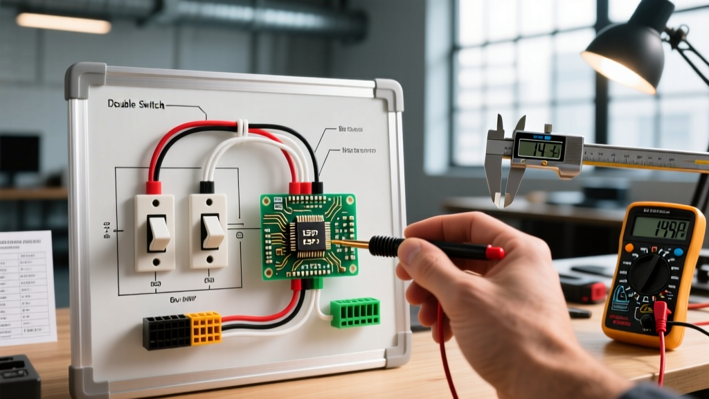
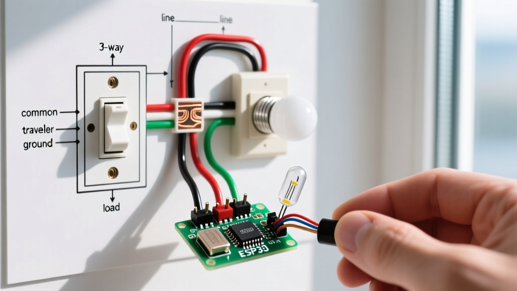
When homeowners and junior electricians search for a wiring diagram for 2 switches and 1 light, they are almost always looking for a standard 3-way switch circuit. In residential electrical terminology, a '3-way switch' refers to the physical switch device (a single-pole, double-throw or SPDT switch) that allows you to control a single lighting load from two separate physical locations, such as the top and bottom of a staircase or opposite ends of a hallway.
Planning this installation before cutting drywall or pulling cable is critical. Unlike a simple single-pole switch loop, a 3-way circuit requires traveler wires to carry the electrical current between the two switch locations. Misjudging the cable types, failing to account for box fill capacities, or ignoring modern neutral wire requirements will result in failed inspections or incompatible smart-home upgrades down the line.
This installation planning guide breaks down the exact materials, National Electrical Code (NEC) requirements, and cable routing topologies you need to execute a flawless 3-way switch installation in 2026.
NEC Compliance and Wire Sizing Matrix
Before purchasing materials, you must align your plan with the latest NEC standards. The most critical code section for modern switch planning is NEC Article 404.2(C), which mandates that a grounded circuit conductor (the neutral wire) must be present at every switch box controlling a lighting load. This ensures compatibility with smart switches, timers, and occupancy sensors that require a complete circuit to power their internal electronics.
According to the National Fire Protection Association (NFPA), failing to pull a neutral to the switch box is a direct code violation in new construction and major renovations. Furthermore, the Electrical Safety Foundation International (ESFI) emphasizes that proper wire gauge selection based on breaker size is the primary defense against residential electrical fires.
Cable Selection Table for 3-Way Circuits
| Circuit Rating | Hot/Neutral Cable | Traveler Cable | Max Load (Watts) | Breaker Size |
|---|---|---|---|---|
| 15 Amp | 14/2 NM-B | 14/3 NM-B | 1800W (1440W cont.) | 15A Single Pole |
| 20 Amp | 12/2 NM-B | 12/3 NM-B | 2400W (1920W cont.) | 20A Single Pole |
Note: NM-B (Romex) is standard for dry, indoor residential applications. If routing through wet locations or underground conduit, you must upgrade to THHN/THWN-2 individual conductors or UF-B cable.
Mapping the Cable Runs: Two Proven Topologies
The physical layout of your room dictates which wiring topology you will use. Below are the two most common, code-compliant methods for routing cables in a 3-way circuit. We will assume a 15-Amp circuit using 14 AWG wire for these examples.
Topology A: Power at Switch 1 → Switch 2 → Light Fixture
This is the cleanest and most common routing method, as it keeps the line voltage and switched voltage logically separated.
- Run 1 (Panel to Switch 1): Use 14/2 NM-B. The Black wire connects to the Common (dark-colored) terminal on Switch 1. The White wire splices to the neutral pass-through. The Bare wire connects to the ground screw.
- Run 2 (Switch 1 to Switch 2): Use 14/3 NM-B. The Black and Red wires connect to the brass Traveler terminals on Switch 1, and the opposite ends connect to the Traveler terminals on Switch 2. The White wire acts as the mandatory pass-through neutral (wire-nut it in both boxes). The Bare wire is grounded.
- Run 3 (Switch 2 to Light): Use 14/2 NM-B. The Black wire connects to the Common terminal on Switch 2 and carries the switched hot up to the light fixture's black (hot) lead. The White wire connects to the light's white (neutral) lead.
Topology B: Power at Light Fixture → Switch 1 → Switch 2
Use this topology when the ceiling fixture is centrally located and the switches are daisy-chained along a nearby wall.
- Run 1 (Panel to Light): Use 14/2 NM-B. Connect directly to the fixture's hot and neutral leads.
- Run 2 (Light to Switch 1): Use 14/3 NM-B. The White wire brings always-hot power down to the Common terminal of Switch 1 (mark it with black electrical tape). The Black wire carries the switched hot back up to the light fixture. The Red wire serves as the neutral pass-through.
- Run 3 (Switch 1 to Switch 2): Use 14/3 NM-B. Black and Red act as travelers. White acts as the neutral pass-through.
Box Fill Calculations: Avoiding the Crowded Box
A frequent failure point in DIY and rushed professional installations is box fill violation (NEC Article 314.16). 3-way switches require more wires than standard switches, and smart switches require massive physical volume for their internal relays and wire nuts.
Expert Calculation for Switch 1 (Topology A):
Using 14 AWG wire (2.0 cubic inches per conductor). You have 1 Line Hot, 1 Pass-through Neutral, 2 Travelers, and 1 Ground (counts as 1 conductor). Total = 5 conductors. Add the switch device yoke (counts as 2 conductors). Total = 7 conductors.
7 x 2.0 = 14.0 cubic inches minimum.
While a standard 14 cu-in box technically passes code for a mechanical switch, we strongly recommend installing 22.5 cubic-inch deep single-gang boxes (like the Carlon B515R-UPC) at both switch locations. This provides ample room for heat dissipation and future-proofing for smart switches.
Component Selection: Mechanical vs. Smart 3-Way
Your planning phase must finalize the exact switch models, as smart switches drastically alter the wiring requirements.
Standard Mechanical 3-Way Switches
The Leviton Decora 5603-2W (approx. $4.50) is the industry standard. It requires no neutral connection at the switch itself (though the neutral must still be present in the box per NEC). It relies purely on mechanical make-and-break contacts. Installation is fast, and the physical toggle provides tactile feedback.
Smart Multi-Location Dimmers
If you plan to use a system like the Lutron Maestro MACL-153M (approx. $68.00) or Lutron Caseta, the planning changes. The master smart switch must connect to the neutral wire in the box to power its wireless radio and LED indicator. Furthermore, instead of running 14/3 traveler wires to the second location, modern smart setups often use a wireless Pico remote (e.g., Lutron PJ2-3BRL) mounted in a wall bracket at the second location. This eliminates the need for Run 2 entirely, saving hours of fishing wire through finished drywall.
Installation Pitfalls and Edge Cases
Even with a perfect wiring diagram for 2 switches and 1 light, physical installation errors can cause frustrating edge cases. Watch out for these specific failure modes:
- The 'Traveler on Common' Error: If the light only turns on when Switch 1 is in the 'Up' position, but Switch 2 does nothing, you have likely wired a traveler wire to the Common (dark) terminal on Switch 1. The Common terminal must always receive the Line Hot (from the panel) or the Switched Hot (to the fixture).
- Shared Neutral Tripping AFCI/GFCI: If your 3-way circuit shares a neutral wire with an adjacent circuit in the panel, the return current imbalance will instantly trip an AFCI or GFCI breaker. The neutral for the 3-way light fixture must originate from the exact same breaker as the line hot.
- Over-torquing Terminal Screws: When terminating 14 AWG solid copper wire on the brass traveler screws of a Leviton switch, do not over-tighten. The manufacturer spec is typically 12-14 in-lbs. Over-tightening shears the copper or crushes the insulation, creating a high-resistance arc fault hazard over time.
- Bootleg Grounds: In older homes lacking a ground wire, never use the neutral wire as a ground (a 'bootleg ground'). If a fault occurs, the metal faceplate of the switch will become energized at 120V. If no ground is available, you must install a GFCI breaker and label the switch 'No Equipment Ground' per NEC 406.4(D).
Final Planning Checklist
- [ ] Verify breaker size (15A or 20A) and match NM-B wire gauge accordingly.
- [ ] Ensure 14/3 or 12/3 cable is purchased for the traveler runs.
- [ ] Confirm deep 22.5 cu-in electrical boxes are on the materials list.
- [ ] Map the exact physical route (Topology A or B) before drilling top/bottom plates.
- [ ] Plan for NEC 300.11 securing: staple NM-B cable within 8 inches of every box and every 4.5 feet along the joist runs.
By treating the wiring diagram for 2 switches and 1 light not just as a schematic, but as a comprehensive physical installation plan, you ensure a safe, code-compliant, and future-proof electrical system.