
The Anatomy of a Modern Trailer Brake Circuit
When towing heavy loads, relying solely on your tow vehicle's braking system is not just illegal in many jurisdictions—it is physically dangerous. According to the SAE J2807 standard for tow vehicle gross combination weight ratings, any trailer exceeding 1,500 lbs should ideally utilize an independent electric braking system. In 2026, while many late-model heavy-duty trucks feature integrated trailer brake modules (ITBM) communicating via CAN-bus, millions of RVs, horse trailers, and flatbeds still rely on traditional aftermarket controllers and standardized multi-pin connectors.
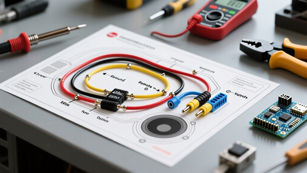
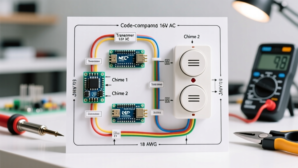
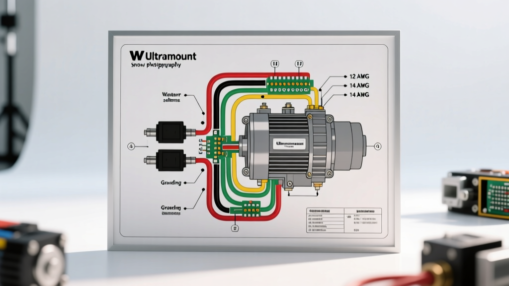
Understanding the correct electric brake wiring diagram trailer layout is the difference between a smooth, synchronized stop and a catastrophic jackknife event. This vehicle-specific guide breaks down the exact pinouts, wire gauge mathematics, and installation protocols for the two most common connector types: the 7-Way RV Blade and the 6-Way Round.
Core Components of the Braking Circuit
Before routing wires, you must identify the four critical nodes in the electric brake circuit:
- The Brake Controller: The brain of the operation. Modern proportional units like the Tekonsha Prodigy P3 (Model 90195, approx. $165) or the Curt Spectrum (Model 51170, approx. $130) use internal accelerometers to sense the tow vehicle's deceleration and output a precise Pulse Width Modulation (PWM) signal to the trailer.
- The 7-Way or 6-Way Connector: The physical bridge transferring 12V DC power and the modulated brake signal from the truck to the trailer.
- The Breakaway Kit: A mandatory safety device featuring a pull-pin switch and a dedicated 12V battery that applies full braking power if the trailer physically detaches from the hitch.
- The Brake Assemblies: Typically 10-inch or 12-inch drum brakes with electromagnetic actuator coils, drawing roughly 3.0 to 4.0 amps each under full load.
7-Way RV Blade Pinout and Color Codes
The 7-Way RV flat blade connector is the undisputed industry standard for travel trailers, fifth wheels, and enclosed car haulers. While physical pin layouts can vary slightly between manufacturers like Hopkins and Bargman, the wire color-to-function mapping is universally standardized. For a comprehensive reference, always cross-check with etrailer's comprehensive wiring FAQ.
| Pin Function | Standard Wire Color | Minimum Wire Gauge | Circuit Notes |
|---|---|---|---|
| Ground | White | 10 AWG (or 8 AWG) | Must ground directly to the tow vehicle chassis. Never rely on the hitch ball. |
| Electric Brakes | Blue | 10 AWG | Carries the PWM signal from the brake controller to the trailer axle magnets. |
| Tail/Running Lights | Green | 14 AWG | Powers clearance lights, license plate lights, and taillights. |
| 12V Auxiliary Power | Black | 12 AWG | Provides continuous 12V to charge trailer house batteries or power interior lights. |
| Right Turn/Stop | Brown | 14 AWG | Combined turn and brake signal for the right side of the trailer. |
| Left Turn/Stop | Yellow | 14 AWG | Combined turn and brake signal for the left side of the trailer. |
| Reverse/Auxiliary | Purple | 14 AWG | Typically wired to reverse lights or a reverse lockout solenoid for surge brakes. |
6-Way Round Pinout (Heavy Duty & Horse Trailers)
The 6-Way round connector is frequently found on older horse trailers, heavy-duty equipment trailers, and some agricultural implements. The primary difference is the absence of a dedicated reverse/auxiliary pin and a different physical layout.
- Center Pin: Ground (White, 10 AWG)
- Pin 2 (Top Left): Tail/Running Lights (Green, 14 AWG)
- Pin 3 (Bottom Left): Left Turn/Stop (Yellow, 14 AWG)
- Pin 4 (Top Right): Right Turn/Stop (Brown, 14 AWG)
- Pin 5 (Bottom Right): Electric Brakes (Blue, 10 AWG)
- Pin 6 (Top Center): 12V Auxiliary (Black, 12 AWG)
Wire Gauge Selection and Voltage Drop Calculations
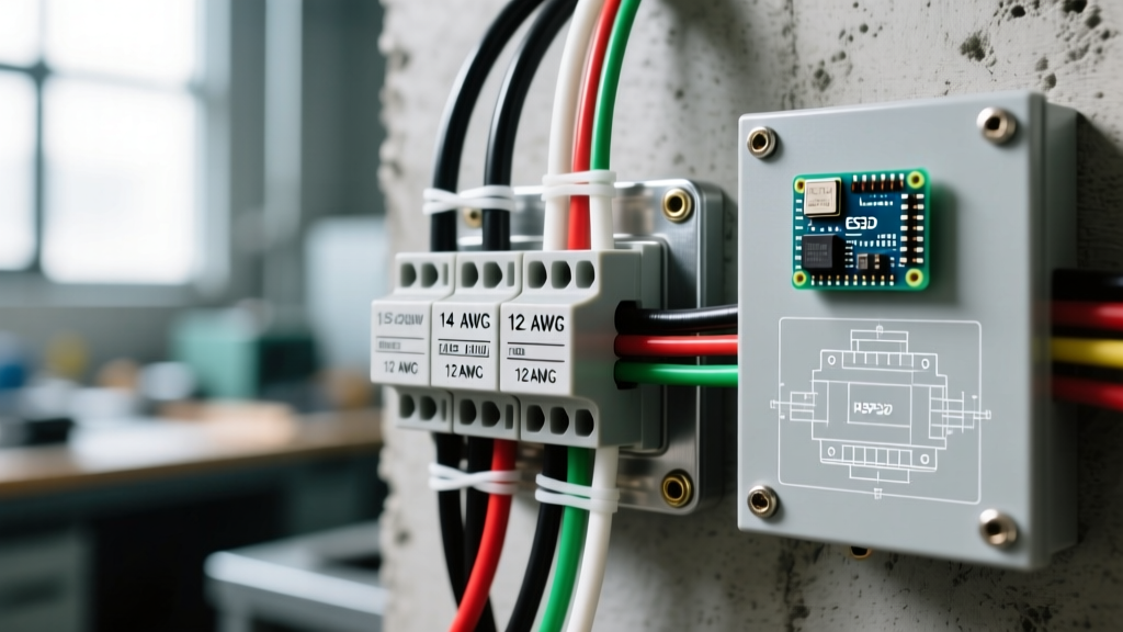
A common and dangerous mistake in trailer wiring is using 14 AWG wire for the electric brake circuit. Electric brake magnets draw significant current. A dual-axle trailer with four brake assemblies will pull between 12 and 16 amps under heavy braking. Using undersized wire causes severe voltage drop, resulting in weak braking performance and overheated wires.
The NHTSA vehicle safety guidelines emphasize the importance of maintaining adequate electrical capacity for towing accessories. Use the chart below to select the correct wire gauge for your Blue (Brake) and White (Ground) wires based on the distance from the tow vehicle's front bumper to the furthest trailer axle.
| One-Way Distance | Total Circuit Length (Round Trip) | Recommended Gauge (at 15A) | Estimated Voltage Drop |
|---|---|---|---|
| Under 15 ft | 30 ft | 12 AWG | 0.80V |
| 15 ft to 25 ft | 30 ft to 50 ft | 10 AWG | 0.75V |
| 25 ft to 40 ft | 50 ft to 80 ft | 8 AWG | 0.62V |
| Over 40 ft | 80+ ft | 6 AWG | 0.50V |
Step-by-Step: Routing and Terminating the Brake Circuit
- Run the Main Harness: Route a jacketed 7-way cable from the trailer tongue to the junction box. Secure it every 18 inches using UV-resistant zip ties, ensuring it does not rub against the leaf springs or the A-frame.
- Terminate at the Junction Box: Inside the trailer's front junction box, strip the jacket and ring-terminal the White (Ground) and Blue (Brake) wires. The White wire must be bolted directly to a clean, bare metal point on the trailer chassis using a star washer to bite through any paint or rust.
- Run the Axle Wires: From the junction box, run 10 AWG Blue and White wires down the trailer frame to the axles. Use split-loom tubing to protect the wires from road debris.
- Wire the Brake Magnets: At each wheel, connect the Blue wire to one terminal on the brake magnet, and the White wire to the other. Note: Brake magnets are non-polarized; it does not matter which wire goes to which terminal.
- Install the Breakaway Switch: Wire the breakaway switch in parallel with the main brake circuit. Connect one side of the switch to the trailer's dedicated breakaway battery (positive), and the other side to the Blue brake wire. If the trailer separates, the pin pulls, closing the circuit and sending full 12V directly to the brakes.
Critical Edge Cases: Ground Fade and Backfeed
Even with a perfect electric brake wiring diagram trailer layout, real-world environmental factors can cause system failure. Here is how to troubleshoot the two most common edge cases:
1. Ground Fade (The Hitch Ball Fallacy)
Many DIYers assume the steel hitch ball provides an adequate ground path between the truck and trailer. This is a fatal error. Rust, grease, paint, and galvanic corrosion between the coupler and the ball create high electrical resistance. When the brake controller demands 15 amps, the voltage chokes at the hitch, resulting in "ground fade" where the brakes apply weakly or pulse erratically. The Fix: Always run a dedicated 10 AWG or 8 AWG White ground wire from the trailer chassis directly to the 7-way plug, and ensure the tow vehicle's 7-way receptacle is grounded directly to the truck's frame.
2. Backfeed and Separate Turn Signals
Modern European vehicles and some heavy-duty American trucks use separate wiring for brake lights and turn signals (a 3-wire system: left turn, right turn, brake). Trailers use a combined 2-wire system. If you wire a 3-wire truck directly to a 2-wire trailer without a converter, pressing the brake pedal can cause the trailer's turn signals to illuminate, or vice versa, causing backfeed into the truck's CAN-bus and triggering dashboard error codes. The Fix: Install a dedicated tail light converter module (like the Tekonsha 119190) that isolates the signals and combines them safely before they reach the 7-way plug.
Final Verification and Controller Calibration
Once the physical wiring is complete, plug the trailer into the tow vehicle. Turn on the truck's running lights and verify all trailer markers illuminate. Have an assistant press the brake pedal while you verify the brake controller's display shows a power output. Finally, perform a low-speed (20 mph) test in an empty lot. Adjust the brake controller's "Gain" setting until the trailer brakes engage firmly without locking up the wheels, and adjust the "Boost" setting to ensure the trailer brakes initiate slightly before the tow vehicle's brakes, keeping the rig perfectly straight during emergency stops.