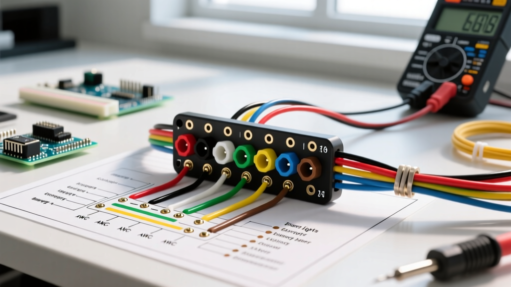

Clarifying the '7-Pin Flat' Terminology
When DIYers and professional mechanics search for a wiring diagram for 7 pin flat trailer connector systems, they are almost universally referring to the standard 7-Way RV Blade connector. Governed by the SAE J286 standard, this connector features a flat, rectangular housing with blade-style pins. It is the dominant standard for North American travel trailers, fifth wheels, and heavy-duty utility trailers in 2026. It is critical not to confuse this with the 7-pin round connector (ISO 1185), which is primarily used in agricultural and European commercial applications. Understanding this distinction prevents catastrophic wiring mismatches that can blow your tow vehicle's lighting control module.
2026 Safety & Tool Loadout
Before cutting a single wire, ensure you have the correct materials. Cheap connectors cause voltage drops and trailer brake failures.
- Wire Strippers: Klein Tools 11063W Katapult (Approx. $24.50) - ensures clean cuts without nicking copper strands.
- Connectors: Ancor Marine Grade 12-10 AWG Heat Shrink Butt Connectors (Approx. $18.99 for 50-pack). The internal sealant prevents moisture intrusion.
- Crimper: Titan 11230 Ratcheting Crimper (Approx. $32.00) for consistent, gas-tight crimps.
- Protection: Permatex 22058 Dielectric Tune-Up Grease (Approx. $7.49) to prevent galvanic corrosion on the blade pins.
- Testing: Fluke 115 True RMS Multimeter or a dedicated Hopkins 40375 Circuit Tester.
Standard 7-Way RV Blade Pinout Matrix
The physical layout of the 7-way blade connector is standardized, but the wire colors and gauges must be matched precisely to handle the specific amperage loads of modern trailer systems. Below is the definitive pinout matrix for the tow vehicle side (male plug) and trailer side (female receptacle).
| Pin Position | Wire Color | Function | Min. AWG | Max Load (Amps) |
|---|---|---|---|---|
| 1 (Bottom Center) | White | System Ground | 10 AWG | 40A+ |
| 2 (Top Right) | Blue | Electric Trailer Brakes | 12 AWG | 20A |
| 3 (Bottom Right) | Green | Tail / Running Lights | 14 AWG | 10A |
| 4 (Top Center) | Black | 12V Auxiliary Power | 10 AWG | 30A |
| 5 (Top Left) | Red | Left Turn / Stop Lights | 14 AWG | 10A |
| 6 (Bottom Left) | Brown | Right Turn / Stop Lights | 14 AWG | 10A |
| 7 (Center) | Yellow | Reverse Lights / Aux | 14 AWG | 10A |
Step-by-Step Wiring Execution Protocol
Proper execution of the wiring diagram for 7 pin flat trailer connector setups requires more than just twisting wires together. Follow this protocol to ensure a weather-tight, vibration-resistant connection.
1. Preparation and Stripping
Strip exactly 5/16 inch of insulation from the end of each wire. Stripping too little results in the crimp barrel biting into the insulation, creating a high-resistance point. Stripping too much leaves exposed copper that will rapidly oxidize and short against adjacent pins.
2. Crimping and Heat Shrinking
Insert the stripped wire into the Ancor heat shrink butt connector. Use the ratcheting crimper to apply a uniform crush. Once crimped, apply heat from a heat gun (set to roughly 250°F) starting from the center of the connector and moving outward. You will know the seal is complete when the internal adhesive melts and slightly extrudes from the ends of the shrink tube.
3. Pin Insertion and Housing Assembly
Feed the wires through the rear cable gland of the connector housing before crimping the pins. Insert each pin into its designated slot until you hear a distinct mechanical click. Apply a generous dab of Permatex dielectric grease to each blade before mating the connector. This displaces moisture and prevents the formation of copper oxide, which is a primary cause of trailer light failure.
Wire Gauge Selection & Voltage Drop Mitigation
One of the most common mistakes when following a trailer wiring diagram is using 14 AWG wire for all circuits to save money. This is a critical error, particularly for the ground and electric brake circuits. According to etrailer's comprehensive wiring guidelines, undersized ground wires are responsible for over 60% of all trailer lighting anomalies.
Let us look at the voltage drop math for a standard 25-foot trailer harness. The formula for voltage drop in a DC circuit is:
VD = (2 × L × I × R) / 1000
Where L is length in feet, I is current in amps, and R is wire resistance per 1,000 feet.
- Scenario A (Electric Brakes on 14 AWG): 25ft run, 12A draw, 14 AWG resistance (2.525 Ω/kft). The voltage drop is 1.51V. On a 12V system, your brake controller is only delivering 10.49V to the brakes, resulting in a 12.5% loss of braking efficiency.
- Scenario B (Electric Brakes on 12 AWG): Same parameters, but 12 AWG resistance (1.588 Ω/kft). The voltage drop drops to 0.95V, delivering 11.05V to the brakes and ensuring full stopping power.
Expert Warning: Never use the trailer chassis as a ground return for high-draw components like electric brakes or 12V auxiliary charging. Always run a dedicated 10 AWG white ground wire directly from the tow vehicle's battery ground to Pin 1 on the trailer connector.
Advanced Troubleshooting & Failure Modes
Even with a perfect wiring diagram for 7 pin flat trailer connector applications, environmental factors and physical stress can cause failures. Here is how to diagnose the three most common edge cases in 2026.
Failure Mode 1: 'Ground Bounce' and Backfeed
Symptom: When you press the brake pedal, the trailer turn signals flash dimly, or the running lights flicker.
Diagnosis: This occurs when the main white ground wire (Pin 1) has high resistance due to corrosion. The current seeks an alternative path to ground, 'backfeeding' through the 14 AWG tail light or turn signal wires. Test the resistance between the tow vehicle chassis and the trailer chassis with a multimeter; it should read less than 0.5 ohms.
Failure Mode 2: Brake Controller Feedback Loops
Symptom: The in-cabin brake controller displays an 'SH' (Short) or 'OL' (Overload) error code immediately upon plugging in the trailer, even when the brakes are not applied.
Diagnosis: The blue electric brake wire (Pin 2) is shorting against the 12V auxiliary black wire (Pin 4) inside the connector housing. This often happens if the wires were not staggered during assembly, causing a bulky joint to pull apart and cross-contact. Disassemble the plug, trim the wires to staggered lengths, and re-crimp.
Failure Mode 3: Modern CAN-Bus Rejection
Symptom: The tow vehicle's dashboard throws a 'Trailer Lighting Fault' code, and the trailer lights do not illuminate, despite the trailer wiring testing perfectly.
Diagnosis: Modern 2024-2026 tow vehicles use multiplexed CAN-bus systems with solid-state relays that monitor current draw. If you upgraded your trailer to low-draw LED lights, the vehicle's computer may think a bulb is burnt out because the current draw is too low. Install a Tow Ready 118137 LED Adapter Module (Approx. $28.00) in parallel with the trailer's running lights to simulate the resistive load of incandescent bulbs.
Frequently Asked Questions
Can I use a 7-pin to 4-pin flat adapter without rewiring?
Yes, plug-and-play adapters (like the Hopkins 47345, approx. $14.99) map the 7-way blade to a standard 4-way flat connector. However, you will lose the electric brake (Blue), 12V Aux (Black), and Reverse (Yellow) circuits. This is perfectly safe for light-duty boat and utility trailers under 3,000 lbs that do not require electric brakes.
Why is my auxiliary 12V pin (Black) not charging my trailer battery?
Most modern factory tow packages isolate the 12V auxiliary pin behind a relay that only activates when the ignition is in the 'Run' position or the engine is operating. Furthermore, a standard 10 AWG wire over a 25-foot run cannot provide enough amperage to charge a deeply depleted deep-cycle battery. For actual charging, install a dedicated DC-to-DC charger (like the Renogy 20A DCC50S) wired directly to a heavy-duty Anderson Powerpole connector, bypassing the 7-way plug entirely.
What is the best way to test the wiring before a long trip?
Do not rely solely on a visual check. Use a dedicated 7-way circuit tester with an integrated load resistor. This device plugs into the tow vehicle's receptacle and uses LED indicators to verify not just continuity, but actual current flow under load, ensuring the vehicle's wiring harness can handle the physical demands of the road.