
Understanding the 2026 Goodman Heat Pump Control Architecture
Interpreting a wiring diagram for Goodman heat pump systems requires a solid grasp of both traditional 24V AC control logic and modern communicating protocols. With the HVAC industry's aggressive shift toward high-efficiency SEER2-compliant units in 2026, Goodman has expanded its lineup of variable-speed inverter heat pumps (such as the DSZC20 side-discharge series) alongside its reliable single-stage and two-stage GSZC18 models. While the fundamental physics of the refrigeration cycle remain unchanged, the electrical control architecture has evolved significantly. A miswired terminal can lead to catastrophic compressor failure, blown control board fuses, or severe efficiency penalties.
Before pulling any wire, technicians and advanced DIYers must identify whether the system utilizes a conventional multi-wire thermostat setup or Goodman's proprietary ComfortNet communicating system. The U.S. Department of Energy emphasizes that proper electrical installation and commissioning are just as critical as the physical refrigerant charging process for achieving rated efficiency and longevity in modern heat pump systems.
Conventional vs. ComfortNet Communicating Systems
Standard Goodman heat pumps rely on an 8-to-10 wire thermostat cable where each wire triggers a specific 24V relay on the air handler control board. In contrast, Goodman's ComfortNet communicating systems use a 4-wire RS-485 serial bus. In communicating setups, the thermostat, air handler, and outdoor condenser share digital data packets rather than simple voltage triggers. This allows the outdoor inverter board to modulate compressor speed in precise increments based on real-time indoor load calculations. Mixing conventional thermostat wiring with communicating outdoor units without the proper Goodman ComfortBridge gateway will result in immediate system lockouts and fault codes.
Decoding the Wiring Diagram for Goodman Heat Pump Terminals
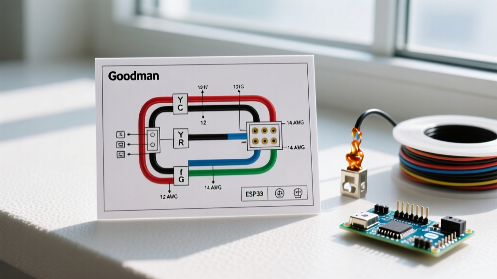
The schematic located inside the outdoor condenser's electrical panel and the indoor air handler's blower access door is your primary roadmap. Below is the definitive breakdown of standard Goodman terminal designations and their operational logic:
- R (Red): 24V AC hot from the control transformer. This provides the baseline power for all thermostat logic.
- C (Blue/Black): 24V AC common. Essential for completing the circuit for smart thermostats and communicating boards. Never borrow a ground or neutral wire to serve as a common.
- Y1 (Yellow): First-stage cooling compressor contactor trigger.
- Y2 (Light Blue): Second-stage cooling or variable-speed ramp-up signal. On single-stage units, this terminal is often unused or repurposed for dehumidification logic.
- W1 (White): First-stage auxiliary or emergency heat. Triggers the indoor electric heat strips or gas furnace relay.
- W2 (Brown): Second-stage auxiliary heat. Engages additional kilowatt banks in the air handler during extreme cold or defrost cycles.
- O (Orange): Reversing valve solenoid energized for cooling. Crucial E-E-A-T Note: Unlike Rheem or Ruud systems that energize the reversing valve in heating (B terminal), Goodman designs its reversing valves to energize in the cooling mode. Wiring this to the B terminal will cause the system to heat when you call for cooling, potentially tripping the high-pressure switch.
- G (Green): Indoor blower motor relay for continuous fan operation.
- E (Dark Blue): Emergency heat toggle. Bypasses the heat pump compressor entirely and locks out the outdoor unit, relying solely on resistive strip heat.
- L (Brown/Black): Fault indicator light. Connects to the thermostat's fault terminal to illuminate an LED when the outdoor unit's diagnostic board detects a hard lockout (e.g., low-pressure switch open).
Wire Gauge, Breaker Sizing, and Disconnect Requirements
High-voltage wiring from the main service panel to the outdoor disconnect, and from the disconnect to the condenser, must be sized according to the unit's nameplate Minimum Circuit Ampacity (MCA) and Maximum Overcurrent Protection (MOP). Never size the breaker based on the unit's Rated Load Amps (RLA); always use the MOP. Below is a reference matrix for standard 208/230V Goodman heat pump outdoor units:
| System Tonnage | MCA (Amps) | MOP (Breaker Size) | Min. Copper Wire Gauge (THHN) | Disconnect Switch Rating |
|---|---|---|---|---|
| 2.0 Ton | 15.2 A | 20 A | 14 AWG | 30 A / 600 VAC |
| 3.0 Ton | 21.4 A | 30 A | 12 AWG | 30 A / 600 VAC |
| 4.0 Ton | 28.1 A | 40 A | 10 AWG | 60 A / 600 VAC |
| 5.0 Ton | 34.5 A | 50 A | 8 AWG | 60 A / 600 VAC |
Disclaimer: Always verify the exact MCA and MOP on the specific unit's data plate, as inverter models and units with factory-installed crankcase heaters may have higher baseline ampacity requirements.
Step-by-Step Indoor Air Handler to Outdoor Condenser Wiring
When routing the control wiring between the indoor air handler and the outdoor heat pump, follow this standardized sequence to prevent cross-connected terminals and ensure proper grounding:
- Power Down & Verify: Kill power at both the main breaker panel and the outdoor fused disconnect. Use a CAT III multimeter to verify 0V across L1 to L2, and L1/L2 to ground.
- Route the Control Cable: Use a minimum 18/8 shielded or unshielded stranded copper thermostat wire for runs under 50 feet. For runs exceeding 50 feet, or for environments with high electromagnetic interference (EMI), upgrade to 16/8 gauge to prevent voltage drop across the 24V circuit.
- Connect the Reversing Valve: Route the orange wire to the 'O' terminal on both the air handler control board and the thermostat baseplate. Secure the solenoid spade connectors at the outdoor unit tightly; a loose connection here causes the reversing valve to chatter, leading to premature solenoid coil burnout.
- Land the Defrost Board Wires: Goodman air handlers utilize a dedicated defrost control board. Ensure the 'DF' (Defrost) terminal on the outdoor board is properly linked to the auxiliary heat trigger. During a defrost cycle, the outdoor fan stops, the reversing valve shifts to cooling, and the indoor strip heat must engage to temper the cold air being pushed through the ductwork.
- Grounding & Bonding: Bond the bare copper ground wire to the designated green grounding lug inside the condenser's electrical box. The National Electrical Code (NFPA 70) Article 250 mandates strict equipment grounding to ensure fault currents have a low-impedance path back to the source, allowing the breaker to trip instantly during a compressor ground fault.
Real-World Failure Modes and Troubleshooting
Safety Warning: Troubleshooting live 240V circuits and 24V control boards requires specialized training. Capacitors inside the outdoor unit can hold lethal charges even after power is disconnected. Always discharge run and start capacitors using a high-wattage resistor before touching internal wiring.
Even with a perfect understanding of the wiring diagram for Goodman heat pump installations, field conditions introduce variables. Here are the most common electrical failure modes encountered by HVAC technicians:
1. The 3-Amp Blown Fuse on the Air Handler Board
If the indoor air handler's 3-amp automotive-style blade fuse blows immediately upon calling for cooling, you almost certainly have a short circuit in the outdoor wiring. The most common culprit is the reversing valve solenoid coil or the contactor coil. Disconnect the orange wire at the outdoor terminal block. If the fuse still blows, the short is in the wire run (often chewed by rodents or pinched in conduit). If the fuse holds, the outdoor coil has shorted to ground. A healthy reversing valve coil should read between 10 and 15 ohms on a multimeter.
2. Inverter Communication Faults (ComfortNet / RS-485)
On 2026 variable-speed models, the indoor and outdoor units communicate via a DC voltage signal superimposed on the AC lines or via dedicated low-voltage communication wires. If the system throws a "Communication Lost" fault code, check the wiring for polarity. While standard 24V AC is non-polarized, RS-485 communicating buses are strictly polarized. Reversing the '+' and '-' or 'A' and 'B' data wires will instantly halt system operation and may damage the transceiver chips on the control boards.
3. Voltage Drop and Contactor Chatter
If the outdoor contactor rapidly clicks on and off (chatter) when the thermostat calls for Y1, the 24V signal is suffering from severe voltage drop. This is common when installers use cheap 20-gauge thermostat wire on long runs (over 75 feet). The contactor coil requires a minimum of 18V to pull in and hold the magnetic field securely. Upgrade to 16 AWG control wire or install a 24V booster relay at the outdoor unit.
NEC Compliance and Safety Mandates
Adhering to the National Electrical Code (NEC) Article 440 is non-negotiable for heat pump installations. Article 440 specifically governs Air-Conditioning and Refrigeration Equipment. It mandates that a dedicated, lockable disconnect switch must be located within sight of the outdoor compressor unit. Furthermore, if the air handler utilizes electric resistance strip heaters (Aux/Emergency heat), NEC Article 424 requires these high-draw elements to be on a separate, dedicated circuit with appropriate overcurrent protection, isolated from the blower motor and control circuits. Ensuring your wiring diagram aligns with these local and national codes protects both the homeowner and the installing contractor from severe liability and fire hazards.